Hardware clock

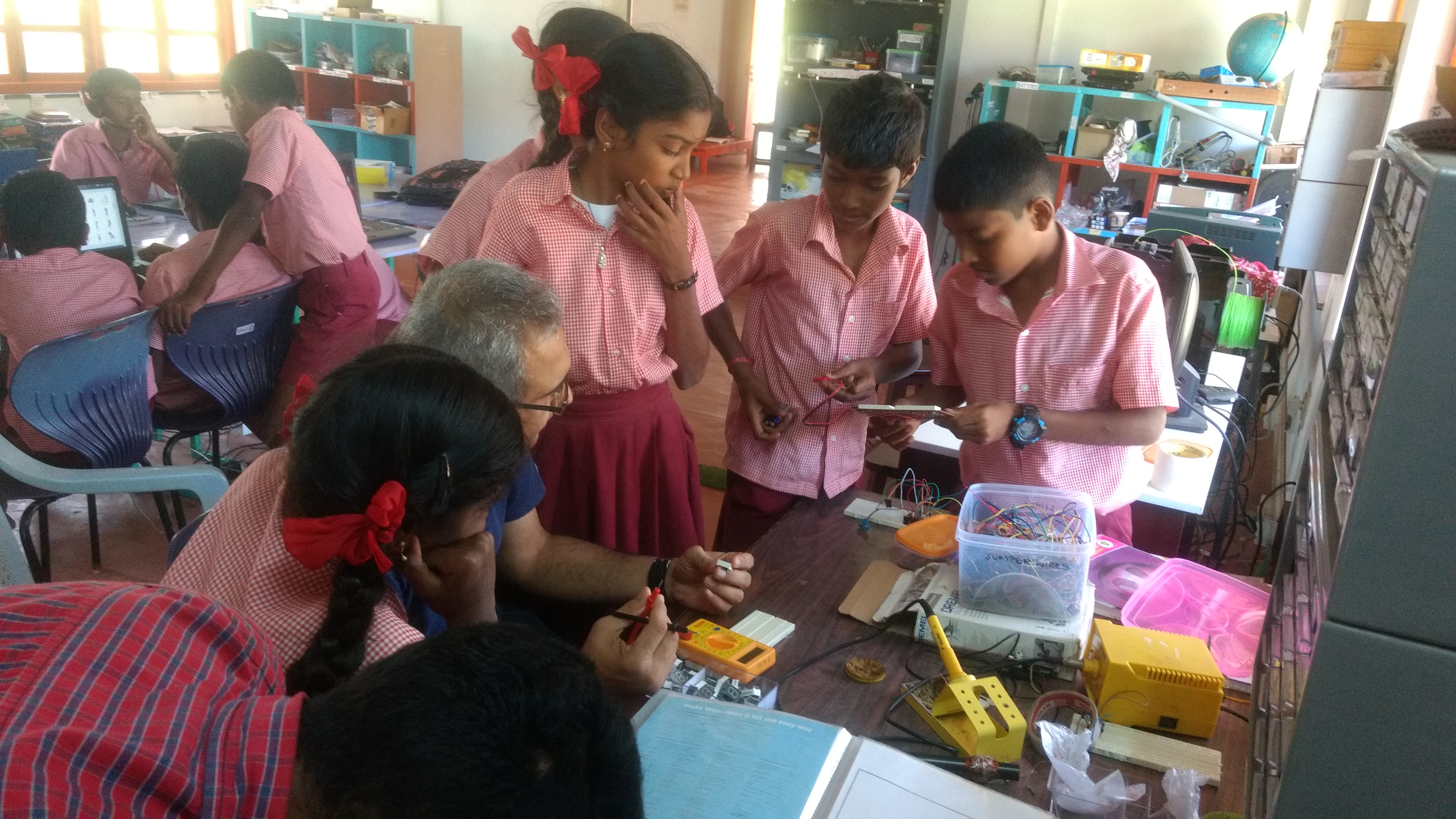
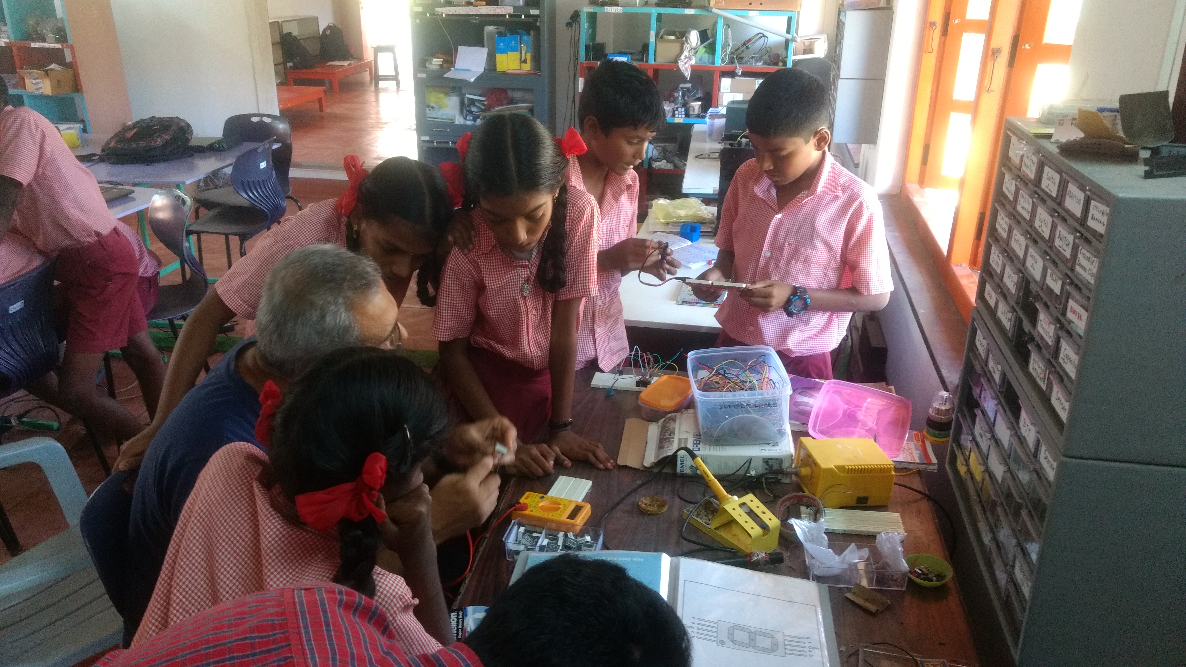
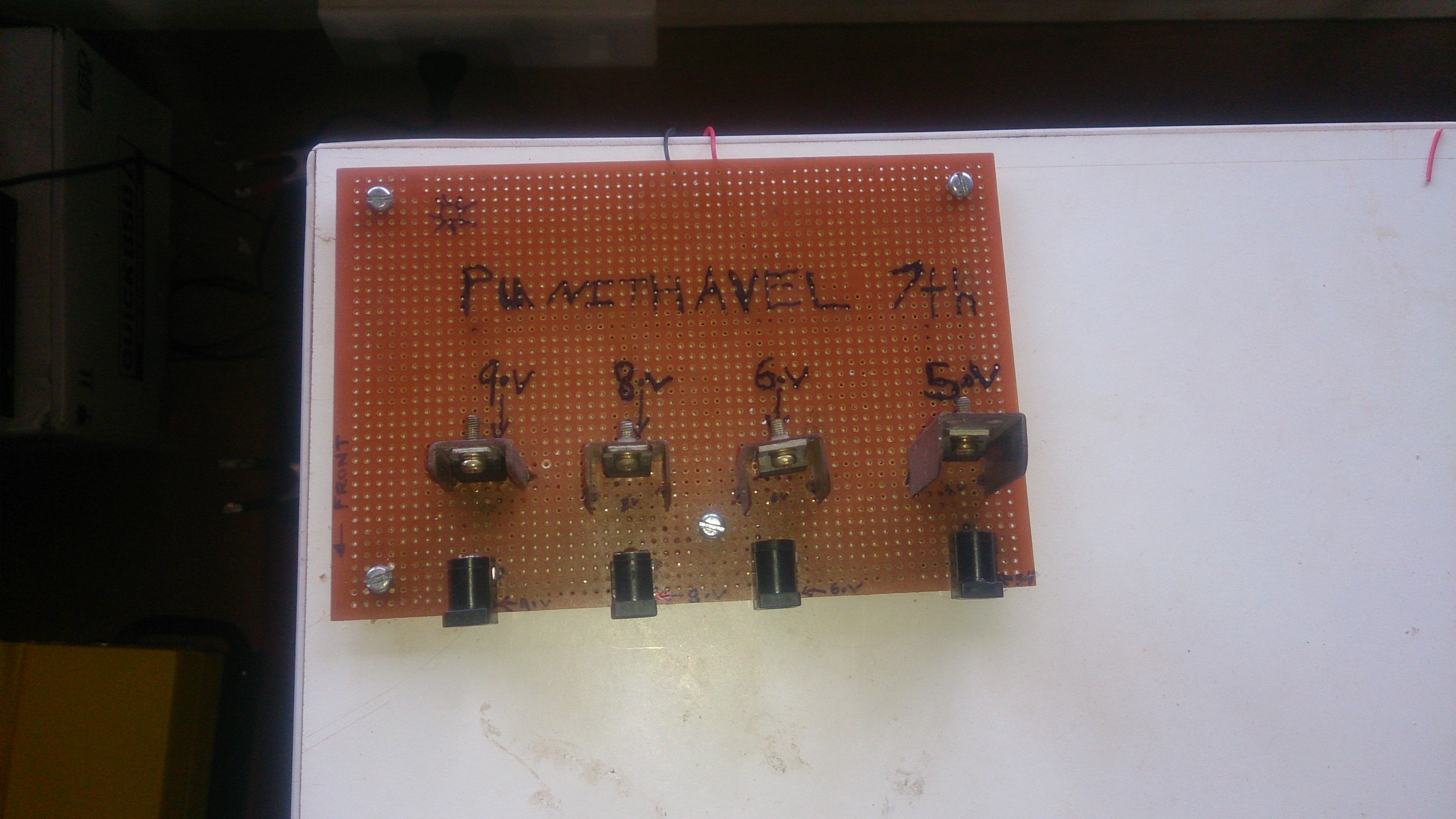
Recently the STEMLAND name board made using SSD had got dim and the 7th std students took it as a project to fix it. They de-soldered the dim SSD’s and Replaced it with new ones.

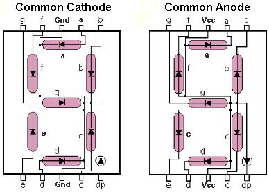
Barani got interested in the SSD’s and started powering them up using the Arduino, he manged to code the Arduino to print all the numbers 0-9 using two SSD’s

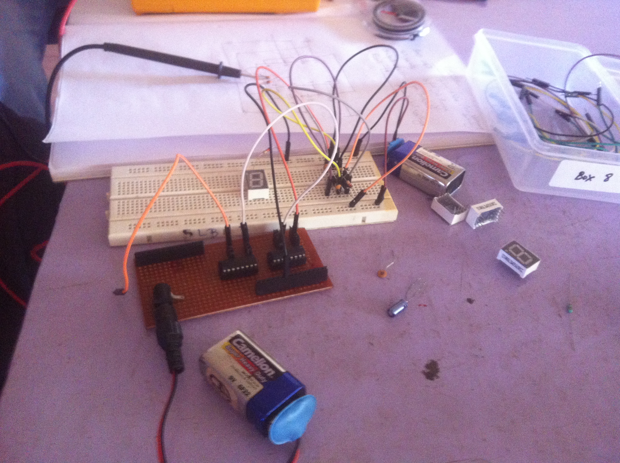
Then to take a step further he started his quest to build a clock. He had added a counter to light the corresponding diodes  in the SSD along with Sanjeev, this was done using a 9V battery.

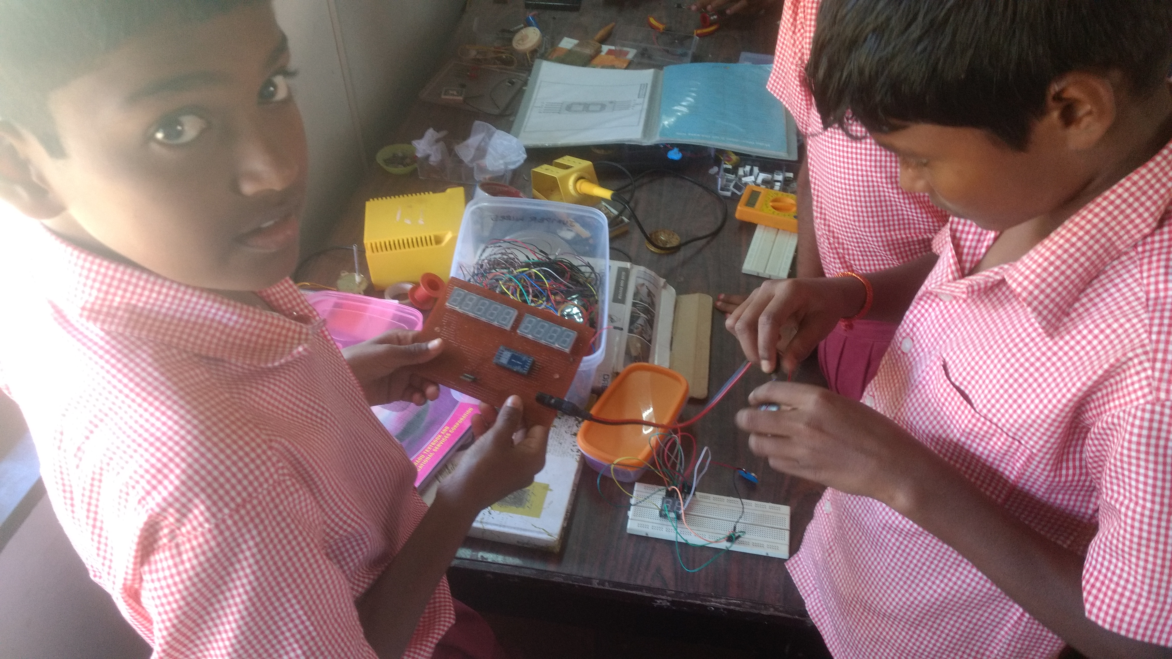
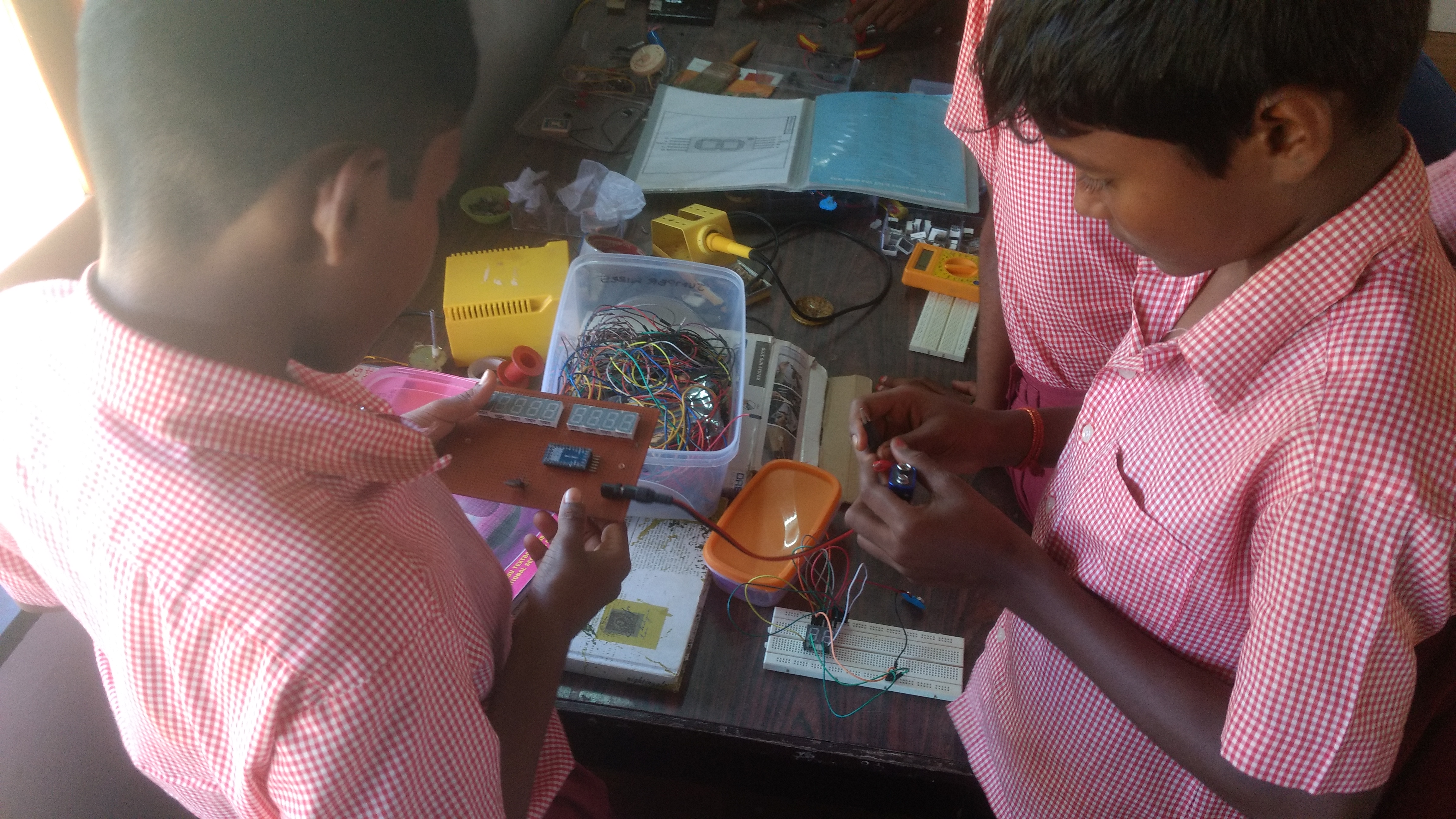
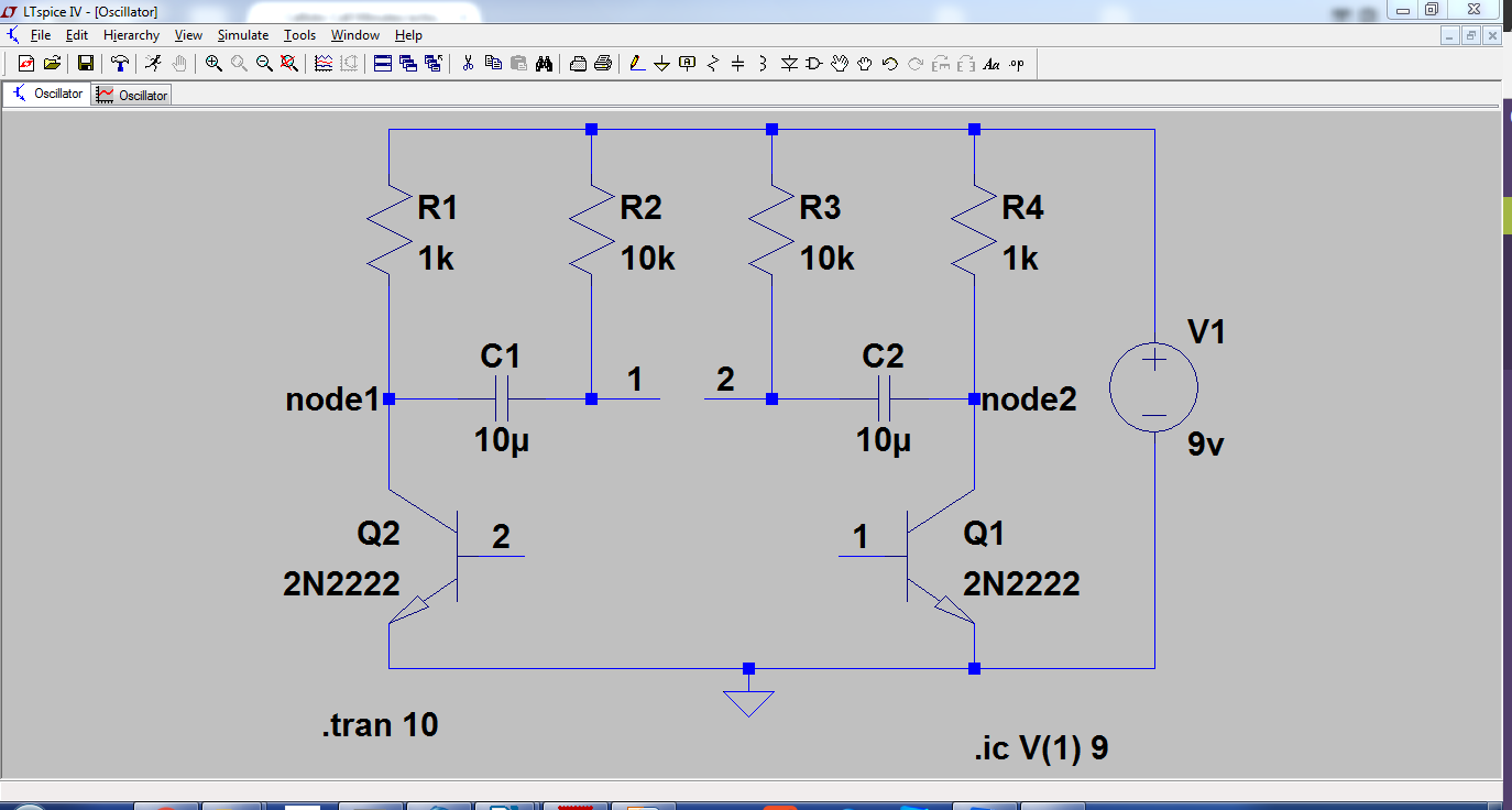
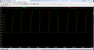
As I already mentioned in my blog that Deepanam children built an oscillator. Bharani used the output of the oscillator as an input and made the clock count from 0 to 9.

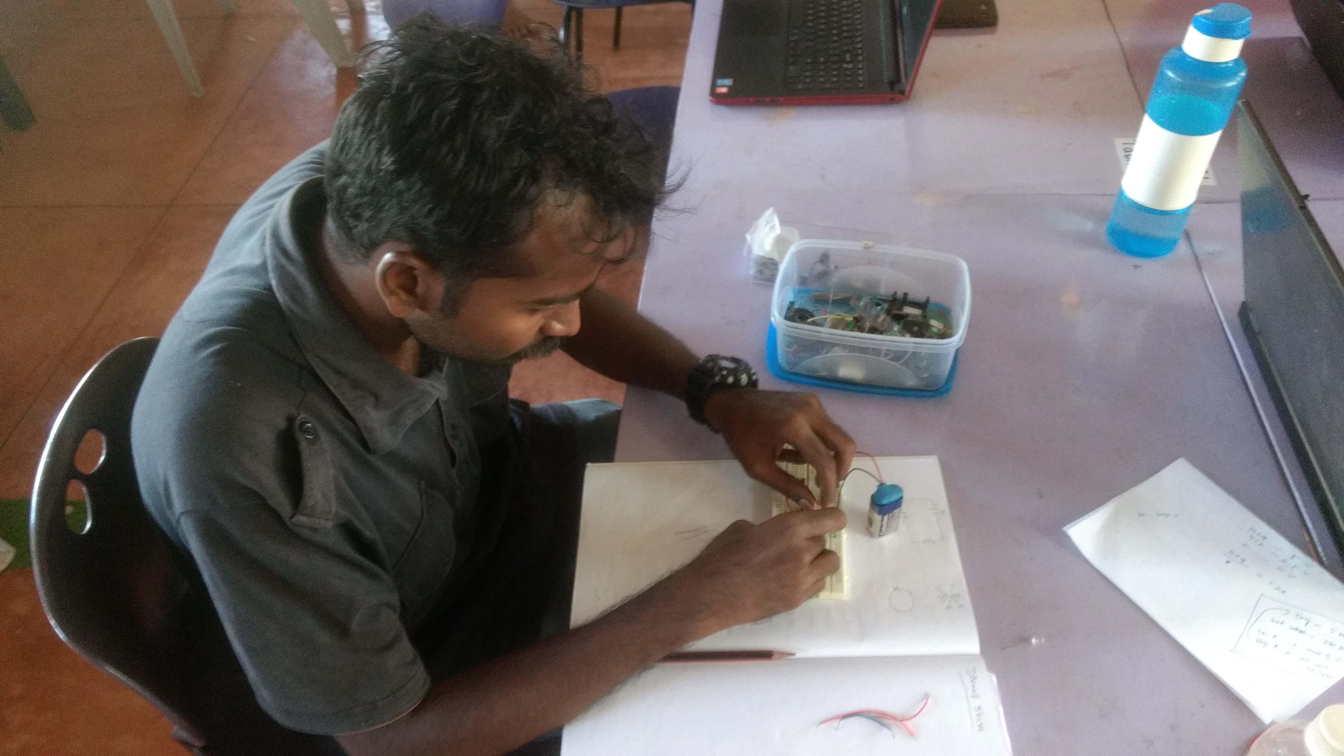
Bharani making the clock count by removing and inserting the input each time.

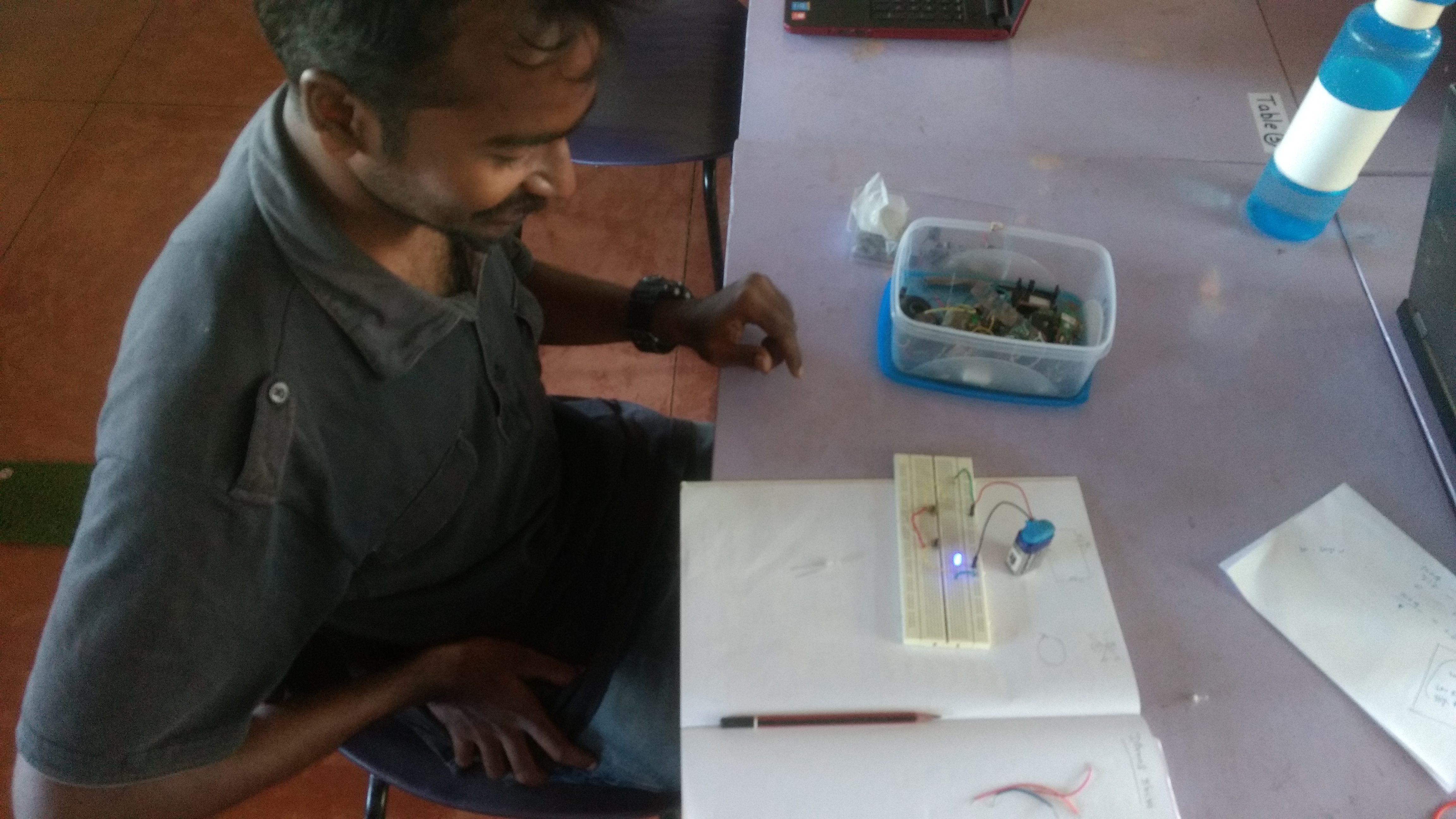
Giving input from the oscillator built by Pravina (Deepanam kid).
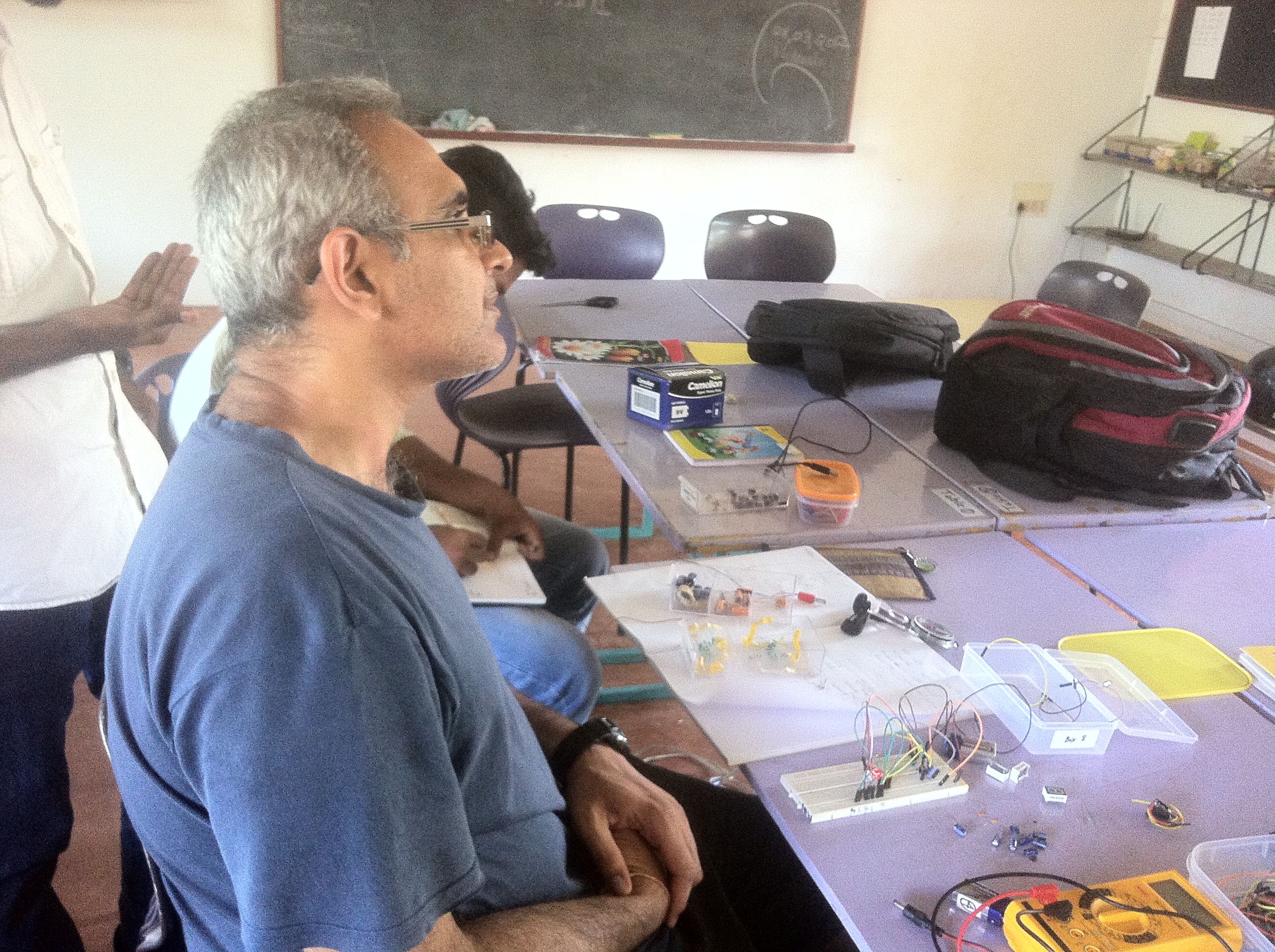
Arun and Sundar


Pre Amp

In Stem land I was trying to repair a preamp which was not working. I opened it and I tried to find the problem. The problem was that the circuit wasn’t connected properly. I made the connection. The preamp needs an Ac input 9 V and 1A  transformer. We bought the transformer and made a cover for the transformer in the Stem land with the 3D printer. The green box was made by 3D printer. Now the preamp works.

Prathap

photo 3(1)IMG_0457I

Fixing STEMLAND name board, and understanding SSD

Some of the 7th std children took fixing the STEMLAND name board as a project, they started off by learning how a SSD (Seven Segment Display) works. Then they assembled the units in a bread board, but there was a bug they couldn’t power up with a 9V battery or else the SSD would burn out. To tackle this they added resistors to control the current. The other bug was some of the SSD were common anode and other common Cathode:SSDOnce the type was figured out the SSD were powered up and tested.

IMG_20170228_133631336 IMG_20170228_133626556 IMG_20170228_133613805 IMG_20170228_133611109

Controlling a single LED using two switches

During the electronic class that is held on every Wednesday afternoon at STEMLAND, Muthu had built a circuit and figured out how to control a LED using two switch model.

His working prototype is as follows:

IMG_20170215_135159801_BURST000_COVER_TOP IMG_20170215_135214467

Video of his prototype:

Two Transistor Oscillator

We built a two transistor oscillator which turns transistors ON and OFF all the time. The speed in which it happens depends upon the value of the capacitor. The higher it is the slower is the process of turning ON and OFF.

Transistor Q2 turns on first as there is now a pathway to ground for C1, C1 begins to charge with its right plate being positive and its left plate being negative through R1.

C1’s right plate reaches a threshold where Q1 is turned on. Turning on Q1 gives a pathway to ground to C2, causing C2 to charge through R2 with a positive voltage on its left plate and a negative voltage on its left.
sch_osc

Simulation of the two transistor oscillator in LT spice.

Output:

op_osc

The green wave represents output of Q2 TRANSISTOR at node1 with reference to ground. The red wave represents output of Q1 TRANSISTOR at node2 with reference to ground.

Creating a Power Supply

In Stemland we got a car battery that was used, and to put it to use we came up with a project of creating a Power supply with various output voltages. To drive  different Circuits with the different potentials. This Project was taken up along with Punithevel (7th std student from Udavi). So to get started, we put together a plan with four output’s. then we decided on the components that we needed and made a list. It consisted of four different power IC’s, connectors and adaptors along with wires. Punithevel had to look up the data sheets of the Power IC’s to figure out the pin configurations for them. Then he came up with the following circuit design.

DSC_0091

DSC_1020The fun part started here when we tried to hook it up on a PCB all the adaptors pins were too big for the given hole on the PCB. Then we put use of our driller set from Stemland and made the required hole at various points on the boards.

The following days we were going through the electronic circuits boards that we have from used devices and decided to de-solder some cool looking heat sinks and salvage them for our circuits 🙂

All the wirings were done taking black for the negative terminal and red for positive terminal. once done the wiring were fragile, and came off when handled roughly. We had the right solution 🙂 the heat gun was put use and the board became robust.

Then we hooked up our board to the work bench again drilling holes and screwing them firmly. following is a picture of the PCB created. We tested it with a multimeter and got the expected output’s, now It works 😉

DSC_0071


Before Testing a Chip or PCB

  • Check model of all components.
  • Check if the board is close to what we expect.
  • Check resistance of the materials.
  • Do the measurements  that can be done without powering it up.
  • Check simulations.

Creating a Spice Model from a .subckt file

The following video demonstrates on how to create a spice model of a component, from a .subckt file which can be acquired from the retailer.

following is a spice model file for a bridge rectifier ; mb6s

data sheet : MB6S_MCC

– Open LtSpice

– Browse for the file and open

– Once opened right click .subckt and create model and design your circuit.

-Ref : http://www.linear.com