
The frequency and the sine wave was set by the function generator. The input, output wave forms were observed from the CRO. The conditions taken were a 50KΩ , 1KΩ and a current source. The input was fed to the 2.1 speaker’s connector jack to produce the sound of the fed sine wave.
|
Frequency (Hz) |
Input (peak to peak value) |
Conditions |
Output (Peak to peak value) |
Observations |
|
600 |
2 V |
50 KΩ |
0.2 V |
Distorted wave |
|
600 |
2 V |
1 KΩ |
2 mV |
Small signal with distorted wave |
|
600 |
2 V |
Current Source |
100 mV |
Distorted wave |
|
600 |
5.5 V |
Current Source |
300 mV |
Not distorted |
|
600 |
5.5 V |
50 KΩ |
100 mV |
Partially distorted |
|
600 |
5.5 V |
1 KΩ |
5 mV |
Bottom of the wave distorted |
|
450 |
11 V |
1KΩ |
8 mV |
Distorted wave |
|
450 |
11 V |
50 KΩ |
200 mV |
Extremely distorted wave |
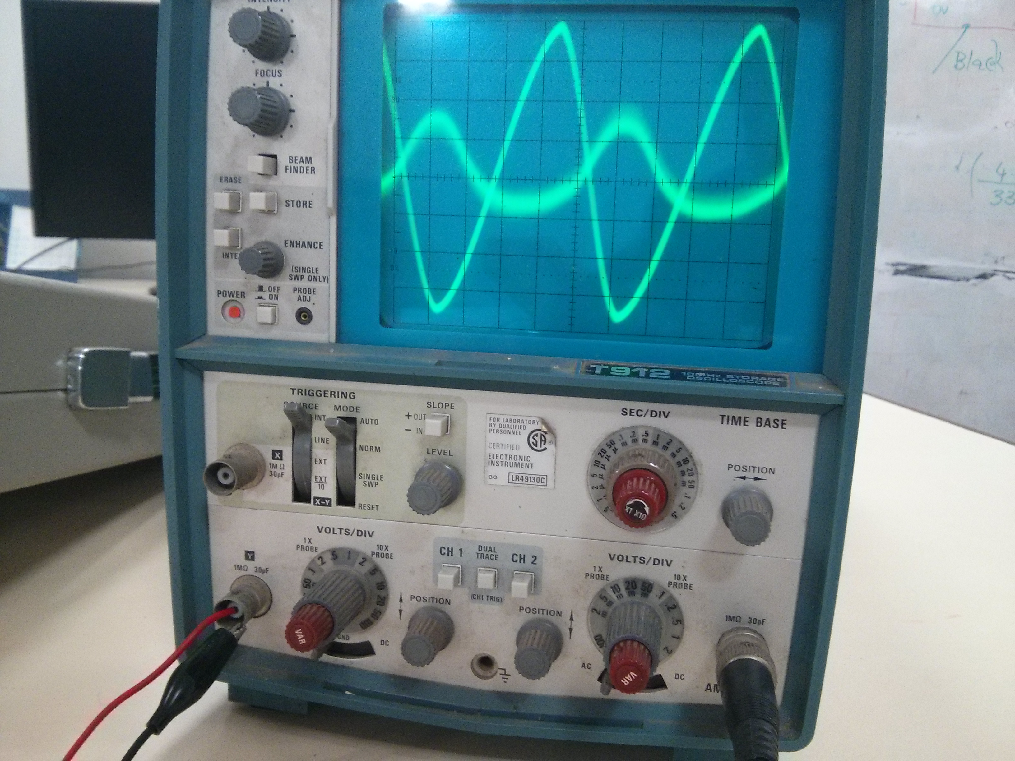
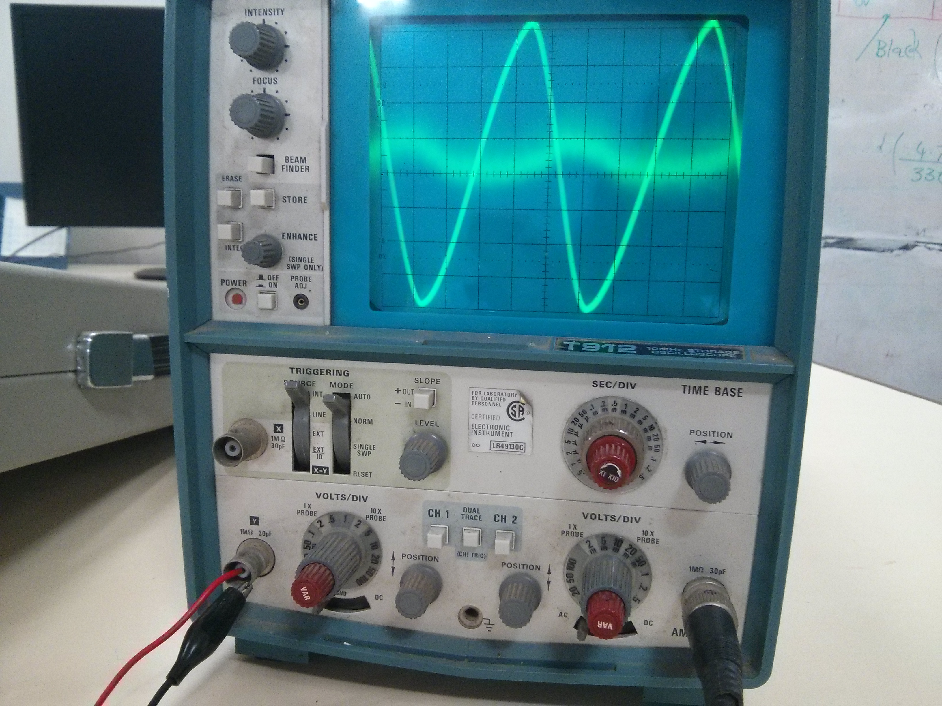
From the tabulation the maximum output 300mV is achieved when the input is set to a peak to peak value of 5.5V connected from the current source (PNP BJT’s collector junction ).
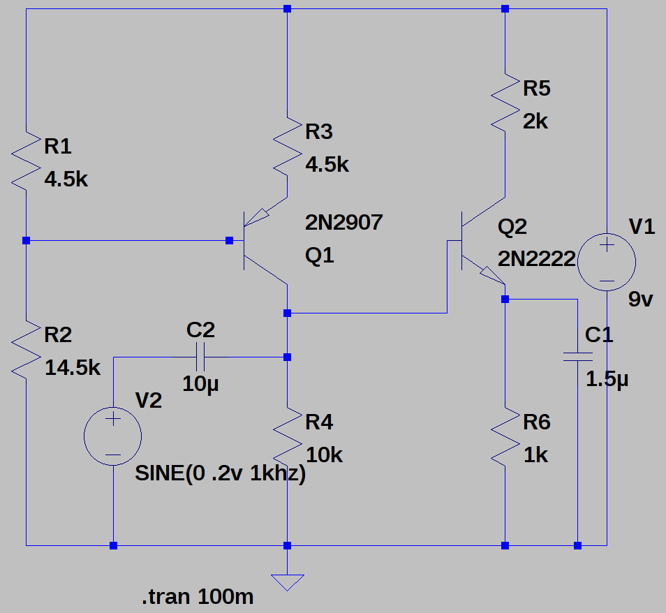 To determine the amplification,
the voltage at the base of the NPN transistors is ≈ 2.5V. now divided by the resistance of resistor R6 gives us the current.
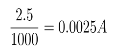
now, the obtained current value multiplied by R5
gives the amplified output ≈ 5V.