Installation of standalone python34

STEP1:

Download python34 (python3.4.0 msi)  from following website,
https://www.python.org/downloads/release/python-340/
After you have installed it go to command terminal(cmd) and put this python in your path as first priority
PATH=C:\Python34;C:\Python34\Scripts;%PATH%     (or)
Go to Control Panel -> System and Security -> System ->  Advanced system settings -> environment variables -> system variables -> path and paste C:\Python34;C:\Python34\Scripts;

STEP2:

Download PySide-1.2.4-cp34-none-win32.whl from https://pypi.python.org/pypi/PySide/1.2.4
In the cmd, cd into the directory where PySide-1.2.4-cp34-none-win32.whl is present and run,
pip install PySide-1.2.4-cp34-none-win32.whl

STEP3:

Download spyder2.3 from https://pypi.python.org/pypi/spyder/2.3.0
In the cmd,
cd spyder-2.3.0
python setup.py install
should install your spyder in the python setup.

STEP4:

Download pyinstaller from https://pypi.python.org/pypi/pypiwin32/219
in the cmd,
pip install pypiwin32-219-cp34-none-win32.whl

STEP5:

Download pyinstaller from https://github.com/pyinstaller/pyinstaller/releases
In the cmd,
cd PyInstaller-3.1.1
python setup.py install

STEP6:

Download xlrd package from  https://pypi.python.org/pypi/xlrd/0.9.3
In the cmd,
cd xlrd-0.9.4
python setup.py install

STEP7:

Download pyglet package from https://pypi.python.org/pypi/pyglet/1.2.3
In the cmd,
pip install pyglet-1.2.3-py3-none-any.whl

STEP8:

Download psutil( download exe since .whl file didn’t work ) from https://pypi.python.org/pypi/psutil 
and run it.
Note:
If you encounter an error saying,
return psutil.phymem_usage().percent AttributeError: ‘module’ object has no attribute ‘phymem_usage’
Open the system.py file:
C:\Python34\Lib\site-packages\spyderlib\utils\system.py
In that file, replace return psutil.phymem_usage().percent line with
return psutil.virtual_memory().percent
StemLand-Name Board

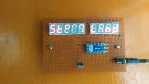
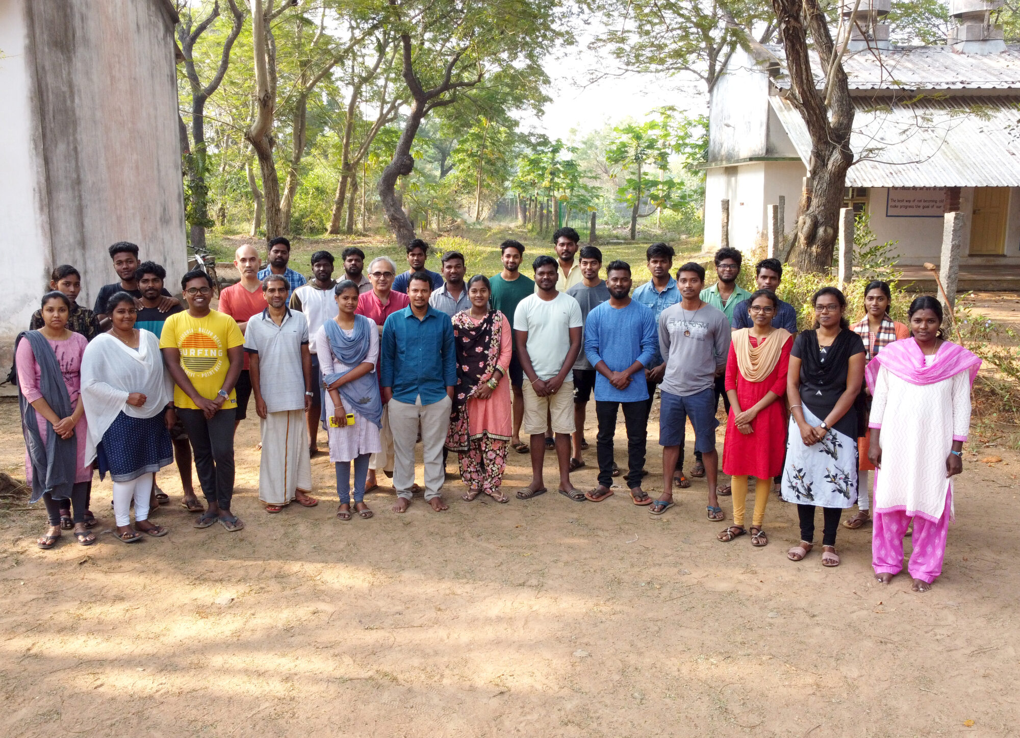
At first the children did a seven segment display(SSD) board which displays StemLand on it by lighting it up using a 9V battery using a corresponding resistor in series. After that we(Anishvathi,Sangeetha,Praveen,Sharmila,Fevina- 8th Grade Students) properly soldered the SSD on a pcb board . We wanted to make the ssd to light up in various ways. So, we used an arduino pro-mini to program the SSD to blink in various ways .We used a battery which was 9V but if we had given the 9V directly it would burn out the arduino board and the SSD.So, we used a 5V voltage regulator which will give us 5V at the output from a 9V input from the battery. Where the output of the regulator is fed to the input of the arduino board. The board worked smoothly. After a few days the battery discharged so we had to change a new battery .

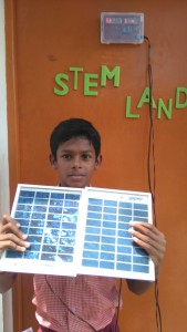
Then Sanjeev gave an idea to make it work using the solar panel . At first Praveen (Student form 8th Grade) and I used one solar panel which did not have enough current to light up the SSDs.So, we used two solar panels in parallel and we got enough current to light up the SSD. Now the board runs in solar energy from the solar panel.

DSC_0708

DSC_0715(Praveen holding the solar panel and displaying how it works)

There is also more detail about this Name Board in the link below

http://www.auraauro.com/showcase/name-board-of-stem-land/


Syringe Generator

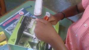
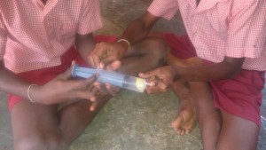
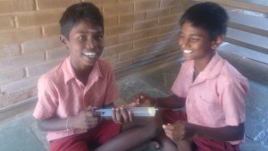
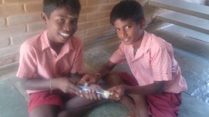
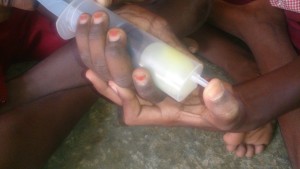
The syringe generator from Arvind Gupta’s Toys was made by few students in the 6th grade. They got the required materials; syringe, enamel wire, Neodymium magnets, and a LED. The children saw the video and came up with their own syringe generator. They also noticed that the led only blinks when the magnet hits one end of the syringe every time they shook it.

DSC_0135 DSC_0136 DSC_0138

Self-Assessment 9th grade

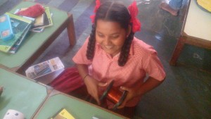
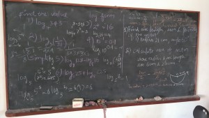
The children of 9th grade were given a self-assessment ‘test’ to make them understand where they are. 4 questions were given on the chapters that they had been working on so far(logarithm and scientific notation). The children were allowed to discuss among them. They graded themselves. We didn’t ask them for marks or how they performed. They would have known it themselves.  It was just a reminder on what they are required to know.DSC_0685 DSC_0684

Stewardship for New Emergence 2016 – Stage I

All Aura Auro team members are attending the Stewardship Workshop this. Some of us have already done satge I of this course. Arun and Naveen are attending it fresh. The session one is over. My biggest realization of session 1 has been the clarity that has come now which was somewhat missing from last years. I got know that I have more ‘fears’ also which I couldn’t also realize last time I did the course. All is well ‘fears’ gives me an opportunity to work from my possibilities.

Compression and Expansion of air

Along with the sixth graders in Udavi we did an experiment that indicated on how air behaves in various pressures. All we needed was a syringe, and a balloon. and we got started. The children took the balloon and kept it inside the syringe and gave pressure. They noticed that the balloon shrunk in size.

DSC_0125 DSC_0122 DSC_0127

This they concluded was because of the intense pressure it created to the captured air.


Then they expanded the air and saw that the balloon drastically increased in size, and this was due to expansion of air and created low pressure.

DSC_0129 DSC_0128 DSC_0131


Creating a Power Supply

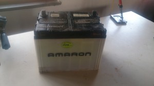
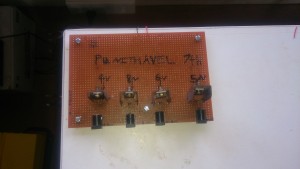
In Stemland we got a car battery that was used, and to put it to use we came up with a project of creating a Power supply with various output voltages. To drive  different Circuits with the different potentials. This Project was taken up along with Punithevel (7th std student from Udavi). So to get started, we put together a plan with four output’s. then we decided on the components that we needed and made a list. It consisted of four different power IC’s, connectors and adaptors along with wires. Punithevel had to look up the data sheets of the Power IC’s to figure out the pin configurations for them. Then he came up with the following circuit design.

DSC_0091

DSC_1020The fun part started here when we tried to hook it up on a PCB all the adaptors pins were too big for the given hole on the PCB. Then we put use of our driller set from Stemland and made the required hole at various points on the boards.

The following days we were going through the electronic circuits boards that we have from used devices and decided to de-solder some cool looking heat sinks and salvage them for our circuits 🙂

All the wirings were done taking black for the negative terminal and red for positive terminal. once done the wiring were fragile, and came off when handled roughly. We had the right solution 🙂 the heat gun was put use and the board became robust.

Then we hooked up our board to the work bench again drilling holes and screwing them firmly. following is a picture of the PCB created. We tested it with a multimeter and got the expected output’s, now It works 😉

DSC_0071