Science Technology Engineering and Mathematics (STEM):

STEM Land:

STEM Land  is a place for ‘Learning’ which we are creating in Udavi school. The vision behind the STEM is learning based on Concepts, practical observation & abstraction. In short “Mediocrity to Excellence“.

It has large variety of materials ( Robot, Physics based materials & kits, Demonstration models, Electronic components & tools, variety of Measurement Equipments, Montessori & Jodo Gyan materials, Strategy games, Puzzles and Books). So we can engage all the students based on their capacity level without letting them feel overburdened  or bored. Most of the students get enthusiastic and become active learners when they get into a new environment ( where the usual text books are absent). So it is added advantage of STEM.

IMG_20150806_103441573-1IMG_20150806_103552028


This three students (7th Grade) have assembled the Robot parts (nearly 300 small pieces). They also programmed the Robot for a challenge I set for them (with guidance). Here they learnt how to be systematic (while assembling the parts of Robot). And became programmers when they started to  program the Robot.

IMG_20150918_163222

IMG_20150912_120227949


This student is an example of perseverance. Many people gave up when they were trying to solve this square puzzle (including me).  One of the reasons was, we got bored. But he pursued  till he reach it. Our curriculum needs this type of activities to empower students to use their creativity to solve problems, ask questions and continually learn.

IMG_20150912_115205909

Students  need to be challenged. At the same time not  be bored. I hope strategy games are one of them which satisfy this condition.  And this made them think and observe keenly without supervision.

LtSpice – Introduction

LTspice IV is a high performance SPICE simulator, schematic capture and waveform viewer with enhancements and models.

The simulator software can be downloaded from the following link:

ltspice.linear-tech.com/software/LTspiceIV.exe

The following is a circuit on how to use a switch ” .model ” in simulations, it has been created for a RC circuit.sw

As seen these switches are not a physical model, they require a initial voltage to start to act as one.

20150820_switch_RC is the simulation file for the given circuit, can be seen by installing LtSpice.


Every switch has some instance of resistance when on or off;
Ron = 1            ‘ the resistance when the switch is turned on.’
Roff = 10meg   ‘ the resistance when the switch is turned off.’
Vt    = 0.1         ‘ the instance when the switch turns on’

Classical way to solve the RC filter in time domain :

RC filter classical time domain way


Area with GeoBoards

I was doing shapes( squares, rectangles and triangle) with 4th and 5th grade children. Then I thought of introducing areas also to them. Doing areas with formulas would be a little difficult for them as they are not yet fully comfortable with multiplication. Then I got to know about GeoBoards. Geoboard is material where children can make all kinds of different shapes they want using rubber bands. It has 64 little squares. Once they make a square or rectangle, all they need to do is to count the number of squares present inside the shape they made. For triangles, we needed to make a rectangle and draw a diagonal so that it makes two triangles inside the rectangle. Area of one triangle is then half the area of the rectangle. As they got more used to it, they didn’t count the little squares anymore and instead they counted the rows and columns to find out the area. Children found it pretty interesting and they could get it quite easily. With material in hand the class is never boring!

DSC_0062DSC_0063

Calling C function from Python using thread

ThreadTest:

Lets loot at a sample program for better understanding of threads. It was written in python extension C( calling C function from python). This is an example for parallel processing. So I made a program to print string ( some words or sentence) after every 4 seconds. But the goal is to modify the default time of printing( delay_time) & string to be printed ( command) without stopping the process (while the program is running). There arise a concept of thread. I used two mechanisms in the code.

1. Global Interpreter Lock (GIL)

2. Mutual Exclusion Lock(MUTEX Lock)

Global Interpreter Lock (GIL) is a mechanism used in computer language interpreters to synchronize the execution of threads so that only one thread can execute at a time. An interpreter which uses GIL will always allow exactly one thread to execute at a time, even if run on a multi-core processor.

The Python interpreter is not fully thread-safe. In order to support multi-threaded Python programs, there’s a global lock, called the global interpreter lock or GIL. Therefore, the rule exists that only the thread that has acquired the GIL may operate on Python objects or call Python/C API functions.

This is so common that a pair of macros exists to simplify it:

Py_BEGIN_ALLOW_THREADS

… Do some blocking I/O operation …

Py_END_ALLOW_THREADS

Mutual Exclusion Lock(MUTEX Lock):

Probably the most commonly used synchronization option to accessing the shared data. Simply, it used to synchronize threads so that only one thread can make modifications to shared data at any given time.

This process is done by two operations,

m.acquire() # Acquire the lock

m.release() # Release the lock

Only one thread can successfully acquire the lock at any given time . If another thread tries to acquire the lock when its already in use, it gets blocked until the lock is released. So it avoids race condition.

Explanation:

Here, I am calling c function from python. To pass the variable to the process , i need to run the process(main) as thread. So i can pass the variable to the main without affecting the program execution. In order to do that i need to create three more python objects to set the value of delay_time, command & quit command.

Program Code:

#include <Python.h>
#include <windows.h>
#include <time.h>
#include <pthread.h>
#include <stdio.h>
#include <stdlib.h>
// Global Variables
int delay_time = 4;
char command_py[10000] = {};
int i;
pthread_mutex_t    command_py_mutex            = PTHREAD_MUTEX_INITIALIZER;
int quit = 0;
// Creating Python Object
static PyObject* ThreadTest_print(PyObject* self)

See More

Python Object:

In the function ThreadTest_set_st(), I declared a character pointer instead of character array is to avoid the the clash between the c and the python while while allocating the  memory  for the local variable (command_local). So i created the pointer for that local variable in which python allocates the memory space.

I also created ThreadTest_set_dt function to prove,  simply getting the user input directly to the variable ‘delay_time‘ could not work at all So one need to be more careful when creating this sort of functions.

Compilation:

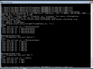
First, i need to run main function as thread. Then, i can pass the string to the main function using following procedures in python terminal.

import Threadtest    //  this used to import the module

import thread         //   this used to import the thread

thread.start_new_thread(ThreadTest.pr, (),)     //  to start the main as thread

ThreadTest.set_st(‘ Hello’)     // to pass the string

ThreadTest.set_st(‘ q’)    // to quit the program

Since, there i made mistake in the ThreadTest_set_dt function i could not call that one. When we modify the ThreadTest_set_dt function according to latter, then this code will print the both function’s arguements .

ThreadTest

Programming the Deek Robot

The Deek robot is similar to the Arduino pro mini with a ATmega 328. it has no USB interface. i used the Arduino UNO to program the Deek robot, without removing the micro controller ATmega 328 from the UNO board.

1. Connect the Arduino UNO and upload the program

2. Connect jumpers as follows
Arduino      UNO               –>         pro mini
RESET             –>         GRN
RX                   –>         RXD
TX                   –>         TXD
5V                   –>         VCC
GND               –>         GND

GND             –>           BLK

Arduino      UNO               –>         DEEK_ROBOT
RESET             –>         RESET
TX                   –>         TXD
5V                   –>         VCC
GND               –>         GND

GND               –>         GRD

Now using Arduino UNO as an ISP, from the Tools, Programmer .

and selecting the board as Arduino Pro or Pro mini (5V,16Mhz)w ATmega 328, from the Tools, Board.

Upload the program.

USING FTDI to program;

FTDI                –>         DEEK_ROBOT
RX                   –>         TXD
TX                   –>         RXD
5V                   –>         VCC
GND               –>         GND

Dt                   –>         DTX

Now  use AVR ISP, from the Tools, Programmer .

and selecting the board as Arduino Pro or Pro mini (5V,16Mhz)w ATmega 328, from the Tools, Board.


Tabulating the obtained values

        The frequency and the sine wave was set by the function generator. The input, output wave forms were observed from the CRO. The conditions taken were  a 50KΩ , 1KΩ and a current source. The input was fed to the 2.1 speaker’s connector jack to produce the sound of the fed sine wave.

Frequency

(Hz)

Input

(peak to peak value)

Conditions

Output

(Peak to peak value)

Observations

600

2 V

50 KΩ

0.2 V

Distorted wave

600

2 V

1 KΩ

2 mV

Small signal with distorted wave

600

2 V

Current Source

100 mV

Distorted wave

600

5.5 V

Current Source

300 mV

Not distorted

600

5.5 V

50 KΩ

100 mV

Partially distorted

600

5.5 V

1 KΩ

5 mV

Bottom of the wave distorted

450

11 V

1KΩ

8 mV

Distorted wave

450

11 V

50 KΩ

200 mV

Extremely distorted wave

IMG_20150511_111205IMG_20150511_111439

From the tabulation the maximum output 300mV is achieved when the input is set to a peak to peak value of 5.5V connected from the current source (PNP BJT’s collector junction ).

5To determine the amplification,

the voltage at the base of the NPN transistors is 2.5V. now divided by the resistance of resistor R6 gives us the current.

amp

 now, the obtained current value multiplied by R5amp1

gives the amplified output 5V.


NPN Transistor as an Amplifier :

  • We wanted to use the transistor as an amplifier.
  • The input voltage at the base was 3v.
  • Two resistors, one at the emiiter(R1) and the other at the collector(aR1) were connected.
  • 9v supply was given at R1.

Constraints :

  • We wanted head room of 2v.
  • We wanted to obtain maximum gain.

Design :

  • Subtracting 0.7v at the emitter from 3v at the base we get 2.3v.
  • Current across R1 is

forAmp1

  • As we needed 2v head room, the voltage drop across aR1 needed to be 4.7v(ie, 4.7v+2.3v=7v) which is 2v lesser then 9v.
  • Current across aR1 is

forAmp2

  • The maximum gain we can get is a gain of 2.
  • Hence the resistor value at the collector should be two times more than the one at the emitter.

amplifier

PNP Transistor as a Current Source

  • We wanted to use a transistor as a current source.
  • Two resistors, one at the emiiter(R1) and the other at the collector(R2) were connected.
  • A voltage divider circuit with a supply of 9v was connected at the base that could supply certain voltage.

Constraints :

  • We wanted 4.5mA of current to pass through.
  • 9v supply was given to the resistor at the emitter.

Design :

  • The resistor at the collector(R2) was chosen as 1k based upon the resistance of the mic.
  • We knew that the diode would turn on at around 0.7v.
  • The voltage drop across R1 should be some resistance that gives 4.5mA of current.
  • Depending upon the availability of the resistors, 330 ohms was chosen for R1, keeping the 9v supply in mind and voltage at emiiter, it was calculated that 1.5v drop would give us 4.5mA of current.
  • Now from the voltage divider, a certain amount of voltage needed to be supplied so that the drop across R1 is 1.5v (ie, 9v – 7.5v)
  • So we wanted 6.8v from the voltage divider (ie, 6.8v + 0.7v = 7.5v)
  • Hence, the voltage divider circuit was designed with the following formula.

forCS

  • The ratio of the scaling factor was approximately 3 and depending upon the availability of the resistors, R3 was taken as 4.7k and R4 was taken as 14.5k.

cs

Amplifier – Simulation and Results

First started with constructing constant current source using PNP transistor with 9V supply voltage.

CONSTANT CURRENT SOURCE:
1


voltage reading:    3.32V                                               current reading:332mA

43

AMPLIFIER:
Added one more transistor on NPN in the circuit with the same supply voltage of 9V and input signal of 0.2V.

Schematic diagram:
6

Simulation Result:

b


Red –> Amplified Output Voltage

Green –> Input Voltage


Schematic diagram:

In order to increase the gain of the Amplifier, added one capacitor C1 parallel with R6 resistor.

5

Simulation Result:
c

Red –> Amplified Output Voltage

Green –> Input Voltage


SpeeDe V_03

SpeeDe V_03:
The aim of the third version of the SpeeDe is to improve the sensitivity to capture the speed of even smaller object. In this regard, I have done some modification in the program ( using the concept of interrupts in Arduino).

ARDUINO PROGRAM:                                                                                                                       // include the library code:
#include <LiquidCrystal.h>
// constants won’t change. They’re used here to
// set pin numbers:
// variables will change:
volatile int State = 0;         // variable for reading the pushbutton status
// Start and stop times
volatile unsigned long start_time_us = 0;
volatile unsigned long stop_time_us = 0;
float delta_time;
float speed_var;

See More

Reference:                                                                                                                             http://www.auraauro.com/uncategorized/speede-v-01-2/
http://arduino.cc/en/Reference/attachInterrupt