Aura Auro Design offers a flipped classroom course to learn electronics hands on at STEM Land (Wed 12:45 to 2:00 p.m.) Here are the videos to aid course content. Some are taken from the web, the other are created by the team at Aura Auro. Most are below 5 minutes, though some with practical demonstration could be 8-10 minutes:
Class 1
1.1 What are charges and a little about static electricity. Here is a fun TeD lesson on the science behind static electricity.
The fun goes a little overboard suggesting that electrons have a negative attitude. This is not true, its an unfortunate convention that makes the flow of current in the reverse direction as the flow of electrons. Of course the convention was created over a century before electrons were discovered. Here is a cartoon suggesting on how this can be fixed.
1.2 Water Analogies for electronics: Water analogies help beginners get a head start in the abstract world of electronics where we cannot really see voltage or current and only see their impact. Here are some explanations that are available online using water as an analogy.
https://ece.uwaterloo.ca/~dwharder/Analogy/ Analogy of a voltage source as a pump that creates a water pressure across it.
https://ece.uwaterloo.ca/~dwharder/Analogy/Resistors/ Analogy for resistor as a sand filter that can slow down the current flow. The finer the sand the more the resistance and more pressure is required across it to have a certain flow of water.
https://ece.uwaterloo.ca/~dwharder/Analogy/Capacitors/ Analogy of a capacitor as a membrane that can store water and maintain a pressure when the main pump is off.
https://ece.uwaterloo.ca/~dwharder/Analogy/Inductors/ Analogy of an inductor as a large water (fly) wheel that is hard to get started and hard to stop.
https://ece.uwaterloo.ca/~dwharder/Analogy/Diodes/ Analogy of a diode as a valve that opens in one direction. There is even one with a LED that also has a fountain to show when here is flow of current.
Limitations of analogies: The first is when the pipe breaks. Air is a reasonably good insulator of electricity and no current flows when there is break in the circuit. In an electronic circuit the current flows in a closed loop. In that sense the pump analogy at least indicates that current needs to flow in a loop, but you expect water to come out of pipes when they are broken. [Note: Air as a insulator can be ionized when a large enough electric field, e.g. lightning or when you short out a car battery]
1.3 What is voltage (DC). Voltage as energy per unit charge and compared to potential energy per unit mass. Viewing voltage in this fashion offers a way to relate voltage to movement, heat, etc.
1.4 What is current: Current the rate of flow of charges through an element can only be measured if the instrument is in series with the element. But measuring it before or after the element gives the same current.
1.5 DC as an average – A DC voltage is the average of the voltage that is varying. As an example a signal generated from an Arduino that is switching between a low and a high voltage. Depending on how much time it is high (duty cycle) you can calculate what voltage will get measured (with demo).
Class 2
2.1 Use of multi-meters in different modes – DC voltage, current, resistance, continuity, etc.[IMPORTANT]
2.2 Introduction to DC power:
2.3 Analysis of Resistor Divider: The resistor has a linear relationship between current and voltage. How do you analyze a resistor divider using this.
Design Exercise in class to use resistors and LEDs to get the maximum light (measured by a LUX meter from 10 cm distance) using a 9V battery and a maximum of 20 mA.
Class 3
3.1 More about LEDs
3.2 Analysis of the max light circuit designed in class 2: A look at efficiency of using power
3.3 Introduction to Simulators (LT Spice Free version): How do you make a circuit in a simulator and simulate a basic DC circuit.[IMPORTANT]
3.4 Kirchoff’s voltage and current law: Even though we will not use the classical analysis that much all analysis will be based off the understanding of the KVL (sum of voltage around a loop is zero) and KCL (sum of currents at a node is zero – no accumulation).
Design exercise in class to build a cube (of the same kind e.g. 10 kOhms) of resistors and predict what the resistance measured between two opposite corners is.
Class 4
4.1 Resistor Network [followup] – How do you measure the resistance between two nodes of a resistive network by feeding a unit current between them measuring the voltage across them.It also has a simulation of a resistor cube.
4.2 Introduction to AC circuits: What is RMS (Root Mean Square)? RMS is used to specify voltage e.g. 240 Vrms (or its whereabouts) in the sockets in India.
4.3 What does a diode do to an AC circuit – explains the rectification process expected from a diode
4.4 All about transformers – Transformers are used to to convert one AC voltage (input – say 240 Vrms) to a different AC voltage (output – say 9 Vrms).
Notes:
1) Doesn’t work with DC voltages/currents.
2) Does not create power and Input power (Vin*Iin) = Output power (Vout*Iout)
Auto transformers (A type of transformers)
4.5 Solving Symmetry Circuits:
Class 5
5.1 – Simulating a transformer in LTspice. As there is no specific transformer model in LTspice unless we create one, this uses inductors coupled together to form a transformer so that we can simulate it.
5.2 – Electromagnetism and Electromagnetic induction:
The video talks about the relationship between magnetism and current.
5.3 MOSFET as Switch
This video is about MOSFET- Metal Oxide Semiconductor Field effect Transistor which is a voltage controlled device and how it can be used as Voltage control switch to light ON and OFF an LED.
5.4 Transformer solution for previous week:
Class 6 : Inductor, Capcitor
Water analogy of inductor.
Capacitor as a filter:
Capacitor water analogy:
Class 7:
7.1. Fun Video on Audio Signals
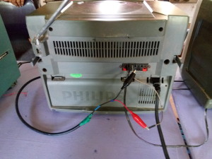
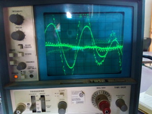
We saw the waveform of the audio signal which was fed from the Radio. Then we added an RC filter and saw how the waveform got smoother.
Class 8:
Capacitor Tap and balloon analogy:
The video shows how capacitor acts in a RC circuit. Both DC and AC voltages explained.


