Tabulating the obtained values

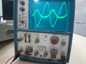
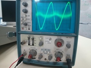
        The frequency and the sine wave was set by the function generator. The input, output wave forms were observed from the CRO. The conditions taken were  a 50KΩ , 1KΩ and a current source. The input was fed to the 2.1 speaker’s connector jack to produce the sound of the fed sine wave.

Frequency

(Hz)

Input

(peak to peak value)

Conditions

Output

(Peak to peak value)

Observations

600

2 V

50 KΩ

0.2 V

Distorted wave

600

2 V

1 KΩ

2 mV

Small signal with distorted wave

600

2 V

Current Source

100 mV

Distorted wave

600

5.5 V

Current Source

300 mV

Not distorted

600

5.5 V

50 KΩ

100 mV

Partially distorted

600

5.5 V

1 KΩ

5 mV

Bottom of the wave distorted

450

11 V

1KΩ

8 mV

Distorted wave

450

11 V

50 KΩ

200 mV

Extremely distorted wave

IMG_20150511_111205IMG_20150511_111439

From the tabulation the maximum output 300mV is achieved when the input is set to a peak to peak value of 5.5V connected from the current source (PNP BJT’s collector junction ).
5To determine the amplification,

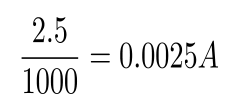
the voltage at the base of the NPN transistors is 2.5V. now divided by the resistance of resistor R6 gives us the current.

amp

 now, the obtained current value multiplied by R5amp1

gives the amplified output 5V.


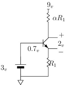
NPN Transistor as an Amplifier :

  • We wanted to use the transistor as an amplifier.
  • The input voltage at the base was 3v.
  • Two resistors, one at the emiiter(R1) and the other at the collector(aR1) were connected.
  • 9v supply was given at R1.

Constraints :

  • We wanted head room of 2v.
  • We wanted to obtain maximum gain.

Design :

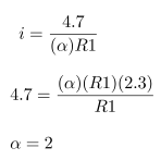
  • Subtracting 0.7v at the emitter from 3v at the base we get 2.3v.
  • Current across R1 is

forAmp1

  • As we needed 2v head room, the voltage drop across aR1 needed to be 4.7v(ie, 4.7v+2.3v=7v) which is 2v lesser then 9v.
  • Current across aR1 is

forAmp2

  • The maximum gain we can get is a gain of 2.
  • Hence the resistor value at the collector should be two times more than the one at the emitter.

amplifier

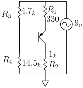
PNP Transistor as a Current Source

  • We wanted to use a transistor as a current source.
  • Two resistors, one at the emiiter(R1) and the other at the collector(R2) were connected.
  • A voltage divider circuit with a supply of 9v was connected at the base that could supply certain voltage.

Constraints :

  • We wanted 4.5mA of current to pass through.
  • 9v supply was given to the resistor at the emitter.

Design :

  • The resistor at the collector(R2) was chosen as 1k based upon the resistance of the mic.
  • We knew that the diode would turn on at around 0.7v.
  • The voltage drop across R1 should be some resistance that gives 4.5mA of current.
  • Depending upon the availability of the resistors, 330 ohms was chosen for R1, keeping the 9v supply in mind and voltage at emiiter, it was calculated that 1.5v drop would give us 4.5mA of current.
  • Now from the voltage divider, a certain amount of voltage needed to be supplied so that the drop across R1 is 1.5v (ie, 9v – 7.5v)
  • So we wanted 6.8v from the voltage divider (ie, 6.8v + 0.7v = 7.5v)
  • Hence, the voltage divider circuit was designed with the following formula.

forCS

  • The ratio of the scaling factor was approximately 3 and depending upon the availability of the resistors, R3 was taken as 4.7k and R4 was taken as 14.5k.

cs

Amplifier – Simulation and Results

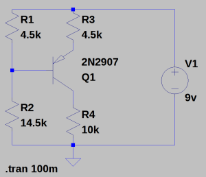
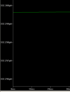
First started with constructing constant current source using PNP transistor with 9V supply voltage.

CONSTANT CURRENT SOURCE:
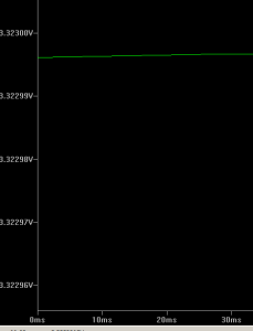
1


voltage reading:    3.32V                                               current reading:332mA

43

AMPLIFIER:
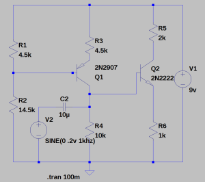
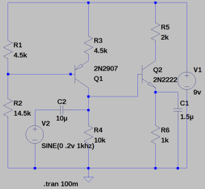
Added one more transistor on NPN in the circuit with the same supply voltage of 9V and input signal of 0.2V.

Schematic diagram:
6

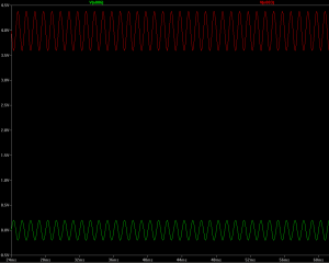
Simulation Result:

b


Red –> Amplified Output Voltage

Green –> Input Voltage


Schematic diagram:

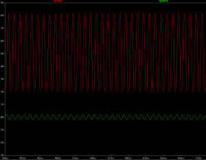
In order to increase the gain of the Amplifier, added one capacitor C1 parallel with R6 resistor.

5

Simulation Result:
c

Red –> Amplified Output Voltage

Green –> Input Voltage