Smart dustbin using Arduino

The smart dustbin is built on a microcontroller-based platform Arduino Uno board which is interfaced with the Servo motor and ultrasonic sensor. An ultrasonic sensor is placed at the top of the dustbin which will measure the stature of the dustbin. The threshold stature is set at a particular level. Arduino will be programmed in such a way that when someone will come in front of the dustbin the servo motor will come into action and open the lid for the person to put the waste material into the dustbin. The lid of the dustbin will automatically open itself upon the detection of a human hand.

Servo Motor:

SERVO MOTOR is an electromechanical device that produces torque and velocity based on supplied current and voltage. It can push or rotate an object with great precision. Servo Motor SG-90 is used. It will perform its angular rotations when a signal will be provided by the microcontroller. The servo motor rotates approximately 180 degrees (90 in each direction).

Infrared sensor:

IR SENSOR is a radiation-sensitive optoelectronic component with spectral sensitivity in the infrared wavelength. It is used for object detection.

Connections: –

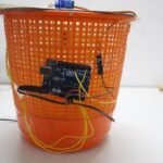
The Red Pin of the Servo Motor is connected to Arduino 3.3v. The Black Pin of the Servo Motor is connected to Arduino GND (Ground). The Orange Pin of the Servo Motor with Arduino Pin 8. VCC of the sensor is connected with Arduino 5v.

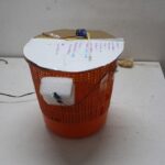
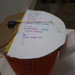
The Smart Dustbin as you can see in the picture above is built using Cardboard. This is a custom-made Smart Dustbin equipped with HC-SR04  Sensor, Arduino, and a Servo Motor. It is programmed using the Arduino code.

Code:

#include<Servo.h>
Servo myservo;
int angle = 0;
int angle step= 50;

void setup(){
myservo.attach(8);
pinMode(2,INPUT_PULLUP);
}
void loop() {
if(digitalRead(2) == HIGH){
myservo.write(180);
}
else{
myservo.write(-180);
delay(3000);
}

Once there is no one in front of the  Sensor the Smart Dustbin Lid remains closed.

The smart dustbin is a carefully designed solution that solves the social issue of waste disposal.

 

Sri Aurobindo 150th celebration talks with Aurovilians: Sanjeev

As part of the 150th Sri Aurobindo’s birth Anniversary, On the 24th of August 2022, Dr.Sanjeev Ranganathan had a live talk with the Aurovillians in Savitri Bhavan.

Dr. Sanjeev Ranganathan is the executive of the Isai Ambalam school, Sri Aurobindo International Institute of Educational Research (SAIIER), and RTL Academy. He received his Ph.D. in Electronics from Columbia University in New York City. He is motivated by his growth as a human being and supports the same in others.

Sanjeev is the recipient of the Lewis Winner award for best paper at ISSCC. He also volunteered for Asha for Education in various capacities and interacted with over 100 NGOs in India working on education. He has worked at Silicon Labs, NXP, ST-Ericsson, and Aura Semiconductor and has built chips used by over a billion people.

He addressed the Aurovillians with his inspiring talk by quoting his life instances with the guidance of Mother and Sri Aurobindo. While volunteering for Asha for Education he perceived Education’s purpose is not to just fit in something but also about standing out. It brought him to Auroville in 2000. He started working on alternative education. He focused on how are we going to support the next generation to do something unique.

He organized education conferences to have accelerated learning. He wanted to create a place for people to learn, experience, and contribute. He explored tribal villages and he did Vipassana, a 10-day silent meditative course that gave him a great feel about the right things to do. He also had a spiritual experience while doing his meditation and saw every being connected. All of us are connected. Once we stop judging people, life becomes easy and amazing.

Sanjeev is passionate about developing critical thinking skills with children and helping them learn and connect with their deepest selves. He believes that this can be achieved by deep meaningful educational experiences for both facilitators and children in the schools, at STEM Science Technology Engineering Mathematics centers, and Aura Auro Design, a technology business he coordinates. In time he created Aura Auro/STEM Land that allows youth to learn, grow, work, and teach as a research project and then a sub-unit of SAIIER.

He always followed the ideologies of Mother and Sri Aurobindo in his endeavors. At Auroville he was introduced to Radical Transformational Leadership which has tools, templates and distinctions used to create whole systems transformational solutions. These tools helped him explore what the root of his existence was and how he need to let it synthesize his life to let it manifest.

With the guidance of Mother and Sri Aurobindo, he continues to progress and help others progress in the beautiful journey of life.

LOGIC GATES USING ARDUINO UNO

A basic gate is defined as a component with one or more inputs and one output.  The inputs and outputs are all digital.

There are three fundamental gates and a total of seven basic logic gates (plus several derivatives). The gate will set its output to either zero or one, based on the state of the input signals.  It uses the rules of Boolean algebra to determine the output condition. The relationship between the input and output logic levels on a gate can be best illustrated using what is known as a truth table.

Simulating Gates with an Arduino:

All of the Boolean algebra functions performed by the basic logic gates can also be emulated on an Arduino. With that in mind, a logic gate emulator that will emulate six of the seven basic gates has been constructed. It doesn’t include the NOT gate because it only has one input whereas the other gates have two.

Project on logic gates using Arduino Uno board consists of 8 LEDs and 8 resistors for the LEDs and two resistors for the pushbutton switches. The LEDs are connected for the logical output and the pushbutton switches are used for the logical input. The positive terminals of the LEDs are connected to the respective terminals of the Arduino board. The negative terminals are connected to the ground of the Arduino.

The green LEDs are for the logic outputs and the red LEDs are for the input.

The dropping resistors for the LEDs are all 220 ohms.

The two pulldown resistors for the pushbutton switches are 2.2k each.

First, define some Boolean variables to represent the logic states of both the two inputs and six outputs. Next, define some integers to represent the connections to the Arduino from the LEDs and push buttons.

It displays logic states on the serial monitor, so in the Setup routine, initialize the monitor at 9600 bps. The rest of the Setup is used to define the LEDs as outputs and pushbuttons as inputs.

In the Loop, it starts by reading the state of the two pushbuttons, and then displaying the results on the two Red LEDs marked “A” and “B”.

The actual Boolean math consists of the following four characters:

  • NOT =!
  • AND = &
  • OR = |
  • XOR = ^

We use the NOT function (!) to create the NOR, NAND, and XNOR gates.

After determining the Boolean results they are sent to both the serial monitor and the LEDs.  Following a short delay the whole Loop repeats.

Load the sketch and give it a try. Cycle through all four combinations of the two pushbuttons and observe the LED statuses, as well as the status on the serial monitor.

This would be a great training tool for testing our knowledge of digital logic.

Arduino gates using code