Nullator
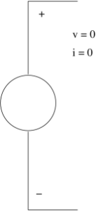
In electronics, a nullator is a theoretical linear, time-invariant one port defined as having zero current and voltage across its terminals. Nullators are strange in the sense that they simultaneously have properties of both a short (zero voltage) and an open current(zero current). They are neither current nor voltage sources, yet both at the same time.
Inserting a nullator in a circuit schematic imposes a mathematical constraint on how that circuit must behave, forcing the circuit itself to adopt whatever arrangements needed to meet the condition. For example, the inputs of an ideal operational amplifier(with negative feedback) behave like a nullator, as they draw no current and have no voltage across them, and these conditions are used to analyze the circuitry surrounding the operational amplifier.
A nullator is normally paired with a norator to form a nullor.
Two trivial cases are worth noting: A nullator in parallel with a norator is equivalent to a short (zero voltage any current) and a nullator in series with a norator is an open circuit (zero current, any voltage).
Norator
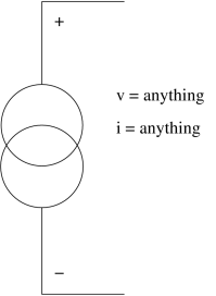
In electronics, a norator is a theoretical linear time invariant one port which can have an arbitrary current and voltage between its terminals. A norator represents a controlled voltage or current source with infinite gain.
Inserting a norator in a circuit schematic provides whatever current and voltage the outside circuit demands. For example, the output of an ideal opamp behaves as a norator, producing nonzero output voltage and current that meet circuit requirements despite a zero input.
A norator is often paired with a nullator to form a nullor.
Two trivial cases are worth noting: A nullator in parallel with a norator is equivalent to a short (zero voltage any current) and a nullator in series with a norator is an open circuit (zero current, any voltage).
Reference : Verhoeven C J M van Staveren A Monna G L E Kouwenhoven M H L & Yildiz E (2003)


