Learning Algebra With the the help of scratch

After finished Geometry i was switched to Algebra. Mastering algebra is important for moving on to nearly all other types of mathematics in  school. However, even the most basic algebra skills can be tricky for beginners to understand the first time they encounter them. I was in the need to know their prior knowledge in algebra in order to build on that (if that was conceptual) or correct them (if that was misconception). So, I gave some equations to solve, asked some stories (Multiplication & Division) and gave them small puzzles  to understand their understandings in algebra.

Except few, all posses some sort of difficulties. Some of them could not able to interpret the question, some of them having difficulties in calculation part, Some were guessed the answers. From that i inferred they need more explanation to understand the concepts. So, i took them to computer lab to practise algebra using scratch programming. First, i gave an expression of 5x+10 and asked them to draw bar graphs in scratch,                                     where x = 1,2,3,4,…….10(with guidance).

Screenshot from 2015-03-13 08:23:18Screenshot from 2015-03-13 08:23:02

Then, i asked them to find out the value of x in the following equation 5x+10=70.

Screenshot from 2015-03-18 16:27:14 Screenshot from 2015-03-18 16:27:45

<iframe allowtransparency=”true” width=”485″ height=”402″ src=”http://scratch.mit.edu/projects/embed/53042546/?autostart=false”

Link: http://scratch.mit.edu/projects/53046628/

What I was  inferred, they could learn(understand) the things comparatively quicker by programming than doing it manually (as procedural). Hence i decided to add one more concept on that just like fun by asking them to draw multi-stair case like structure by modifying the program   ( underScreenshot from 2015-03-13 12:22:31 guidance).


Screenshot from 2015-03-13 12:23:36

<iframe allowtransparency=”true” width=”485″ height=”402″ src=”http://scratch.mit.edu/projects/embed/53046628/?autostart=false”

Link:   http://scratch.mit.edu/projects/53046628/

Mathematics Experiments with 7th Grade Students

The lack of a good education ( sometimes, misunderstanding  or partial understanding of concepts)  is one of the biggest issue across the globe.  Having an educational infrastructure (i.e. schools) is only half the battle. Teacher training is crucial and often the missing element. In order to get a good education children need to have teaching methods which motivate and offer them freedom to learn while in school, and this is where the “chalk and talk” teaching fails.

“Chalk & Talk” is a formal method of teaching with a blackboard and the teacher’s voice as its focal point. This method is used in classrooms across the world. However, this formal and somewhat unimaginative teaching method has come under scrutiny, with many people suggesting that teachers should not rely solely on this technique if they want to engage and inspire their students. Another criticism is that this method of teaching tends to go with the pace of the fastest learner and can leave a lot of children behind. That is, this “Chalk & Talk” method fails to stimulate all the students’ interests in learning. Education needs to be more practical, should allow children to express themselves and learn independently at their own.

So we decided to handle the mathematics class with some programming tool like GeoGebra  ( used to do Geometry) and Sratch ( Syntax free programming). At my first class with 7th graders, i started with GeoGebra. Because, most of the students follow only the procedure not the concepts behind the procedure.

During that period, they learnt about how to draw Equilateral Triangle & Isosceles triangle in GeoGebra (under some different kinds of condition) and their properties. (Here, i enclosed some pictures of my students’ work in Geometry).Screenshot from 2015-03-12 15:35:07

Screenshot from 2015-03-12 15:38:38      This practice made the students to do their text book exercises by their own. Of course, I guess, it took me comparatively more time than “Chalk & Talk” method.

But It doesn’t matter when the students reproduced the things by their understanding.


My First Interaction with Children

My First Proper Interaction with Children (6th graders)

We made a device called ‘SpeeDE’ that measures the speed of an object. We thought that taking this device to school and showing it to the children would be something new to them. One day I took the device to the sixth graders. Everyone saw SpeeDe in my hand and were very eager to know about it.
I started with telling them simple stories on speed and distance.
Eg, I travelled at a speed of 20km/hr, how much distance would i have covered for 3 hrs?

Then i asked the students to make up their own stories. Lots of new stories were made up.
But they had difficulties in the units(km/hr, m/s). They were not completely comfortable with the units.
After most of them had finished telling thier own speed and distance story, it was time to measure something from our device. I started with dropping a pencil case from about a metre to measure the speed of that and asked them to guess the speed. All types of random answers came up.
Then i dropped it from about half a metre and then dropped it from close to the device. The students who were pretty close to right answer were really happy and excited.
Then i asked why does the speed vary when I drop the pencil case from different heights. Some managed to tell that as the height increases the speed of the object also increased which was pleasing to hear.
Then at the end of the class we measured the speed of their punch and kick etc..
Everything was totally a new experience for me. I came to know that handling a class is not that easy as i expected.
Students tend to get more engaged in the class when we bring hands on stuff or else its not that easy to handle a class !!

DSC_0307 DSC_0315

Wavelength

Wavelength

The wavelength of a sinusoidal wave is the spatial period of the wave—the distance over which the wave’s shape repeats. It is usually determined by considering the distance between consecutive corresponding points of the same phase.

wave

The above figure shows the wavelength at a certain time period(the figure is freezed)

In linear media, any wave pattern can be described in terms of the independent propagation of sinusoidal components. The wavelength λ of a sinusoidal waveform traveling at constant speed v is given by

λ = v/f

where v is called the phase speed (magnitude of the phase velocity) of the wave and f is the wave’s frequency. In a dispersive medium, the phase speed itself depends upon the frequency of the wave, making the relationship between wavelength and frequency nonlinear.

In the case of electromagnetic radiation such as light in free space, the phase speed is the speed of light, about . Thus the wavelength of a 100 MHz electromagnetic (radio) wave is about: divided by 108 Hz = 3 meter.

For sound waves in air, the speed of sound is 343 m/s (at room temperature and atmospheric pressure). The wavelengths of sound frequencies audible to the human ear (20 Hz–20 kHz) are thus between approximately 17 m and 17 mm, respectively. Note that the wavelengths in audible sound are much longer than those in visible light.

Difference between Wavelength and Time Period :

There are two variables. One is time and other distance.

We can draw a curve with respect to time and say the vertical displacement at a particular point which shows the period and amplitude. It is time variant at particular point.

We can also draw a curve with respect to distance at a particular time which shows the wavelength and amplitude.

More animations about wavelength are given :

http://www.animations.physics.unsw.edu.au/jw/travelling_sine_wave.htm

Circle Using Scratch

Polar Form of a Circle :
The polar coordinate system is a two-dimensional coordinate system in which each point on a plane is determined by a distance from a fixed point and an angle from a fixed direction. Keeping the radius as constant value(as the radius of the circle of the cant change), the angle keeps on varying until the circle is complete.
1
Here, we have a circle with radius r.
Along the x- axis it is r cos angle and along the y-axis it is r sin angle.
x : r cos angle
y : r sin angle
Circle moved along the axis with radius r :
2
Three circles are shown in the figure.
Each circle has a radius of r(defined by the user).
Center Circle :
The circle at the center has origin of (0,0) and by using the polar form method a simple circle can be drawn by defining the radius r and the angle.
x = r cos angle
y = r sin angle
Circle on the top :
The circle on the top is along y axis. The origin of this circle is at the edge of the center circle on the y axis. So,the equation of this circle is
x = r cos angle
y = r+r sin angle
Circle on the right :
The circle on the right is along x axis. The origin of this circle is at the edge of the center circle on the x axis. So,the equation of this circle is
x = r+r cos angle
y = r sin angle
Drawing a Circle in Scratch using the Trigonometric Formula :
3
There are number ways to draw a circle in Scratch. Lets have a look at how to draw a circle using the Trigonometric formula(Polar form).
Simple way to make a circle is to use the Motion Scripts and to use the Move keys and angle (360 degree) etc..
Create Variables :
Example ,
Radius, r = 50
Sides( the more no of sides you put, the more it will look like a circle) = 80
Angle_step(to make it move in small angles) = 360/ sides
Angle = 0 degree
Use the Motion script to tell Scartch where you want to start the circle.
Here it is :
4
In the Loop :
Change the angle by the angle step( so that the angle changes everytime)
Use the formula :
x : r cos angle
y : r sin angle

DC Circuit Analysis of a Capacitor

DC Circuit Analysis with a Capacitor :

In a DC circuit, if we open up a Capacitor, there will be no change in the circuit. We can analyse the circuit by this way.

If for example 9v passes through the Capacitor from a node, the exact 9v will cross the capacitor without any loss.

dc

An ideal capacitor is wholly characterized by a constant capacitance C, defined as the ratio of charge ±Q on each conductor to the voltage V between them.

                                                                               Q=CV

Because the conductors (or plates) are close together, the opposite charges on the conductors attract one another due to their electric fields, allowing the capacitor to store more charge for a given voltage than if the conductors were separated, giving the capacitor a large capacitance.

Sometimes charge build-up affects the capacitor mechanically, causing its capacitance to vary. In this case, capacitance is defined in terms of incremental changes.

DC Condition :

In a network containing one or more capacitors, in a DC state it means that there are NO CURRENTS flowing through any branches in which a charged capacitor is located. Charged capacitors have voltage but not resistance: V= IR is not applicable since no currents flow THROUGH a capacitor. Voltages also correspond to zero.

                                                                              dv/dt =0

SpeeDe V-01

Abstract
In common everyperson able to measure the speed of a vehicle using a speedometer. But it is simply a question mark when we are trying to find out the speed of an action which end up within micro second. For this scenario we introduced an instrument named SpeeDe which can measure the speed for our intended actions.                                                                                               
Introduction
This paper is dealing with SpeeDe an instrument that can measure the speed of any object that passes through the instrument (provided it crosses the two lasers).                                  Tools Required
Arduino Board & Wooden board
Software Required
Arduino 1.0.6
Components Required
Laser – 2, LDR ( Light Detecting Resister) – 2, Resisters (1kΩ) – 2,Liquid Crystal Display (JHD162A), Printed Circuit Board (PCB) & Potentiometer ( 1kΩ)
Arduino Board
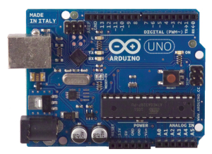
The Arduino Uno is a micro controller board based on the ATmega328. It has 14 digital input/output pins (of which 6 can be used as PWM outputs), 6 analog inputs, a 16 MHz ceramic resonator, a USB connection, a power jack, an ICSP header, and a reset button. It contains everything needed to support the microcontroller; simply connect it to a computer with a USB cable or power it with a AC-to-DC adapter or battery to get started. The Uno differs from all preceding boards in that it does not use the FTDI USB-to-serial driver chip. Instead, it features the Atmega16U2 (Atmega8U2 up to version R2) programmed as a USB-to-serial converter.

Arduino1Microcontroller
Arduino is a microcontroller on a circuit board which makes it easy to receive inputs and drive outputs. A microcontroller is a integrated computer on a chip.                                 Inputs: Some exaples of inputs would be a temperature sensor, a motion sensor, a distance sensor, a switch and so fort. In this project we make use of 10 pins of Arduino as described follows,

 aaa

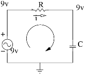
Outputs: Some examples of outputs would be a light, a screen, a motor and so forth.          TL;DR: Arduino is a small computer that you can program to read and control electrical components connected to it.                                                                                                    Arduino do not Read the resistance value. So here we used voltage divider as the part of the connection.                                                                                                                             Wooden Board                                                                                                                             The purpose of the wooden board is to hold the circuits and laser pointers.                             Arduino1.0.6                                                                                                                                                You’ll need to download the Arduino Software package for your operating system.When you’ve downloaded and opened the application you should see something like this:

Ardui2
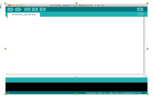
This is where you type the code you want to compile and send to the Arduino board.

arduino3

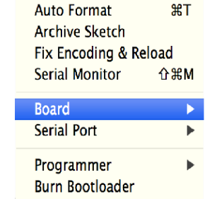
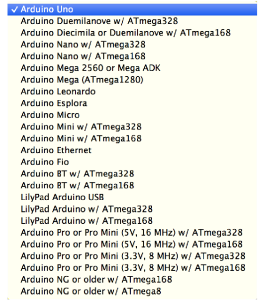
The Initial Setup:                                                                                                                             We need to setup the environment to Tools menu and select Board.Then select the type of Arduino you want to program, in our case it’s the Arduino Uno.

Ar4

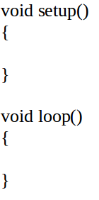
The Code:                                                                                                                                     The code you write for your Arduino are known as sketches. They are written in C++.            Every sketch needs two void type functions, setup() and loop(). A void type function doesn’t return any value.The setup() method is ran once at the just after the Arduino is powered up and the loop() method is ran continuously afterwards. The setup() is where you want to do any initialisation steps, and in loop() you want to run the code you want to run over and over again.                                 So, your basic sketch or program should look like this:

aaa

In our code above the setup() method let’s introduce somth. In C++ we need to state why type our variable is before hand, in this case it’s an integer, so it’s of type int. Here is the program which dumped in the Arduino board.

SpeeDe Program

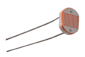
If encounter with the error “ serial port ‘/dev/ttyaCM0’ not found” just execute sudo chmod a+rw /dev/ttyACM0” command in the terminal. Each line is ended with a semicolon (;).                    Light Dependent Resister                                                                                                                 A photo resistor or light-dependent resistor (LDR) or photocell is a light-controlled variable resistor. The resistance of a photo resistor decreases with increasing incident light intensity in other words, it exhibits photo conductivity.

ldr
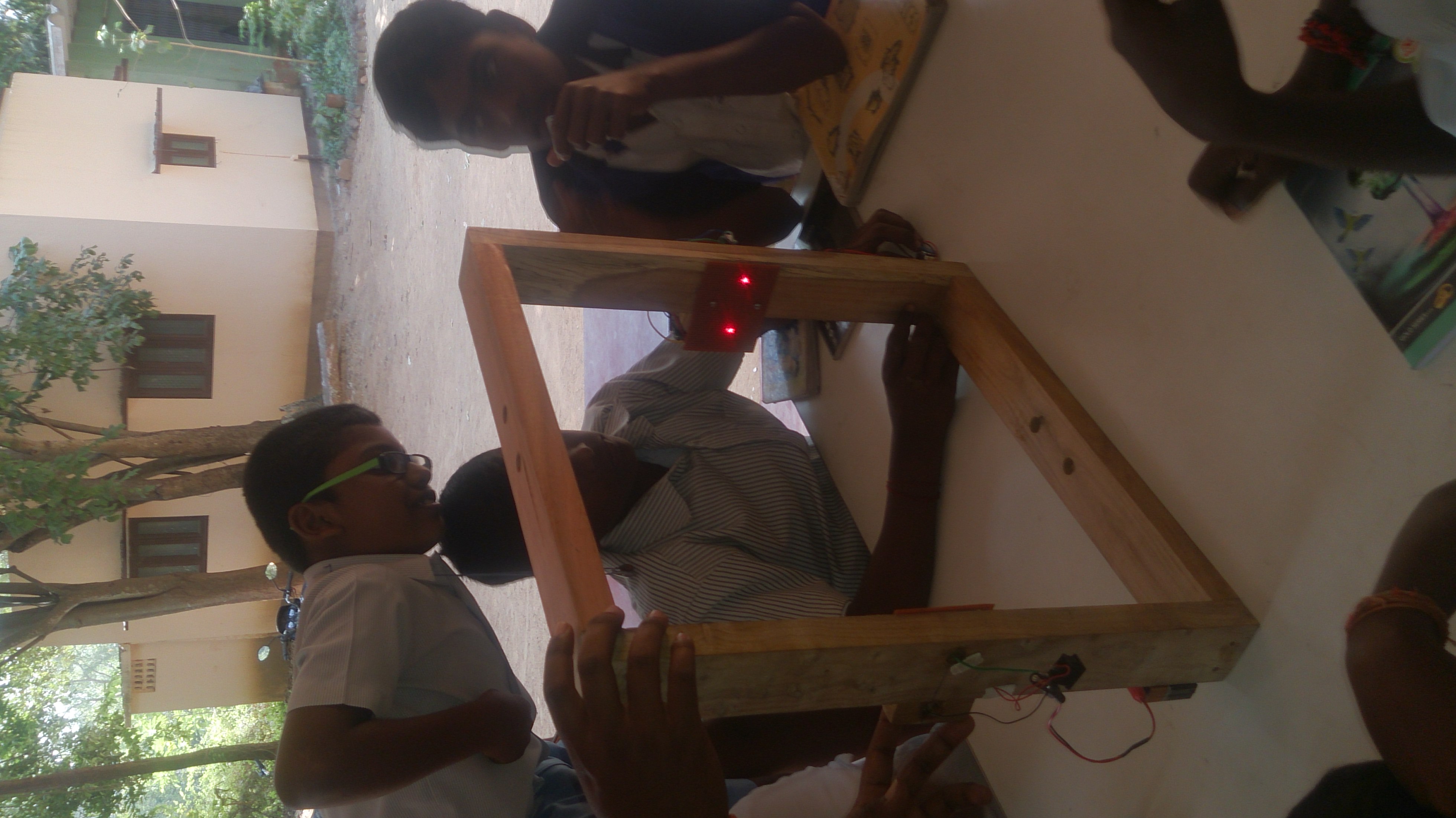
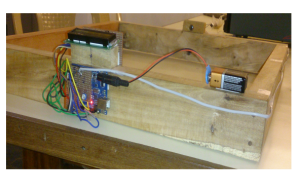
Set up & Working                                               Two Light Dependent Resisters (LDR) were positioned just opposite to two Laser pointers in a printed circuit board in order to vary the resistivity of the LDRs accordance with the lasers get ON and OFF.                                                                     Here the purpose of putting two photo resisters is to detect the time interval of the obstacle which prevent the laser to hit the LDR. As mentioned above when the laser hit the resister its resistivity goes down upto some point & returns back to the original value when the light source gets switched off. By measuring the time interval between the 1st LDR that changed its resistivity and the 2nd LDR that returned back to its original resistivity, one can determine the time interval taken by the obstacle at that instant.                                                                                                                                               Liquid Crystal Display                                                                                                                    
 la

disp2
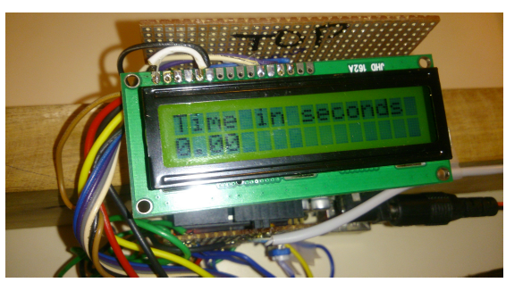
Liquid Crystal Display JHD162A used to display the output of SpeeDe. That is, this set up helps to show the time period of the action and speed in m/s & km/h.

disp1

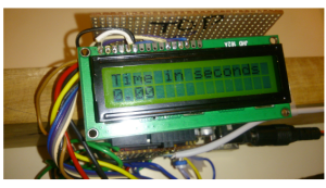
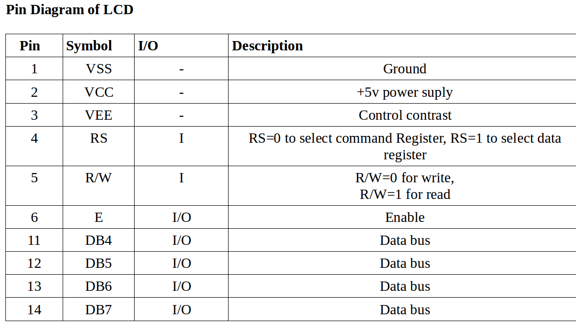
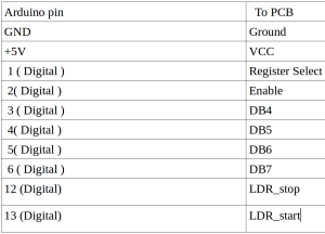
LCD Set up:                                                                                                                                  The first thing is to do is what figure out the LCD pins to be connected with the Arduino board to write the output in the LCD as shown in figure below.

  • VSS & VCC are connected to arduino board’s ground & 5v supply pins.

  • RS, E, DB4, DB5, DB6, DB7 are connected to 1,2,3,4,5,6 ( digital pins of arduino).

  • VEE connected to the potentiometer.

  • Output pins are connected to 12 & 13 ( digital pins of arduino).

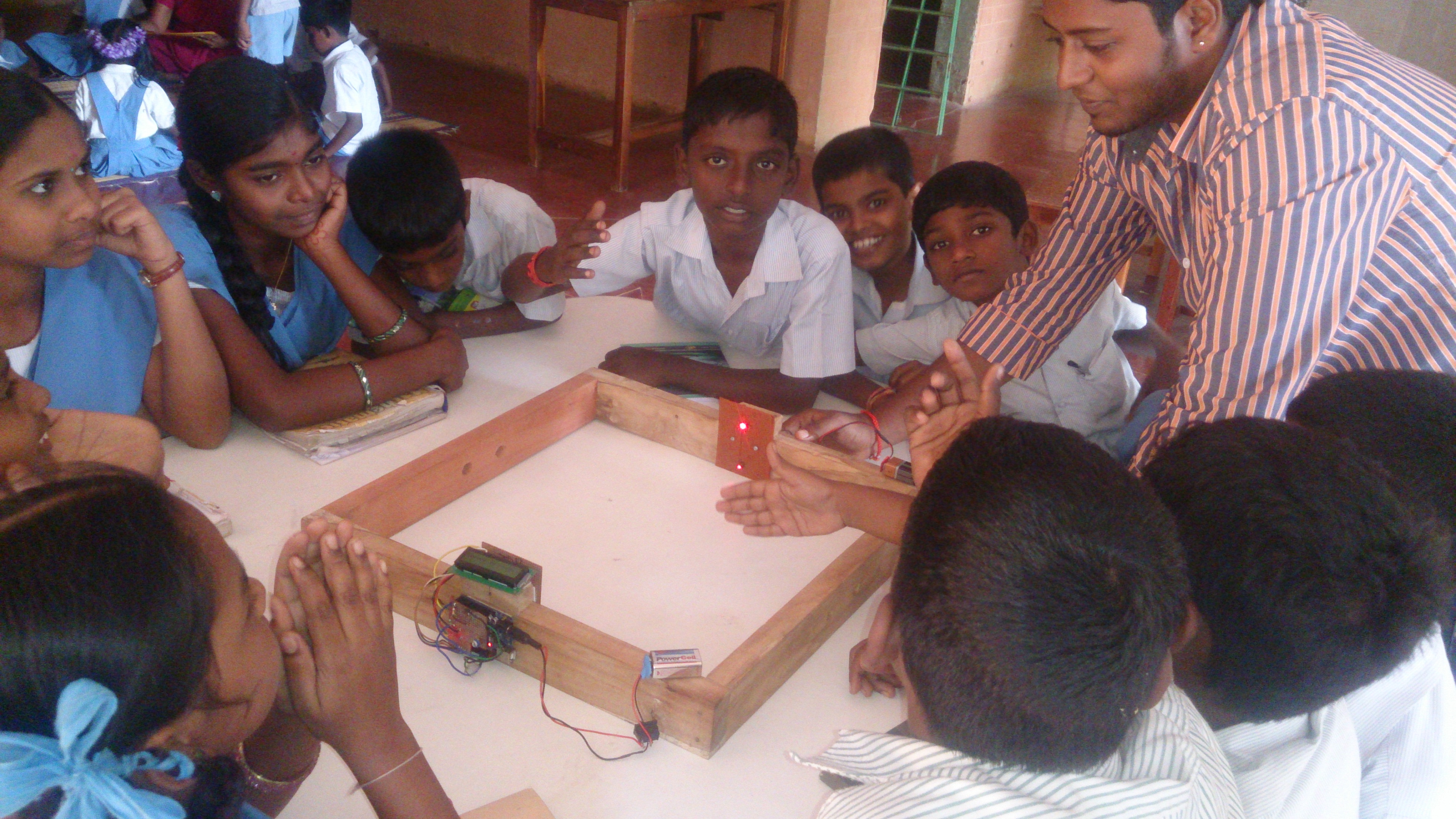
Speede:                                                                                                                                               After integrating all the components in their position as per the design, Speede is ready. This gives the time period of an action, speed in m/s & km/h.

REFERENCE                                                                                                            https://www.google.co.in                                                                        http://www.circuitstoday.com/interfacing-lcd-to-arduino                                     http://www.technologystudent.com/elec1/ldr1.htm                                                                         http://arduino.cc/en/Reference/attachInterrupt