×

We built a two transistor oscillator which turns transistors ON and OFF all the time. The speed in which it happens depends upon the value of the capacitor. The higher it is the slower is the process of turning ON and OFF.

Transistor Q2 turns on first as there is now a pathway to ground for C1, C1 begins to charge with its right plate being positive and its left plate being negative through R1.

C1’s right plate reaches a threshold where Q1 is turned on. Turning on Q1 gives a pathway to ground to C2, causing C2 to charge through R2 with a positive voltage on its left plate and a negative voltage on its left.
sch_osc

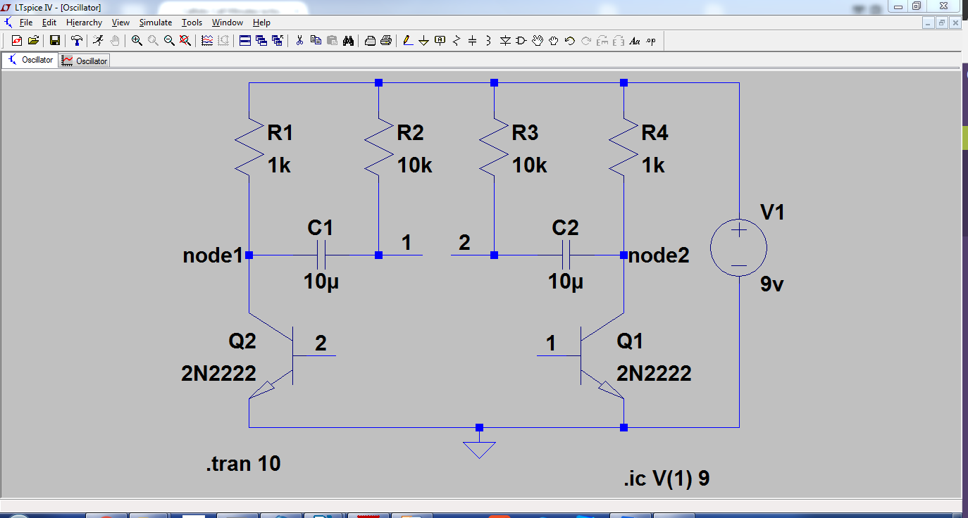
Simulation of the two transistor oscillator in LT spice.

Output:

op_osc

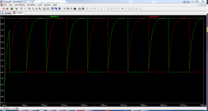
The green wave represents output of Q2 TRANSISTOR at node1 with reference to ground. The red wave represents output of Q1 TRANSISTOR at node2 with reference to ground.

Author

prathap7618@gmail.com

Related Posts

Ardiuno Projects

~ Sivaraman Arduino projects are done for the learning of embedded systems programming. In simple terms, this supports make projects that are...

Read out all

Cycle Safety light

For quite a long time (year and a half), kids in the electronics lab have been working on breadboard circuits which they...

Read out all

Ambient light sensor using a photoresistor and Arduino Uno

This project is about using a photoresistor along with an Arduino Uno board to determine the brightness of a room which is...

Read out all

Smart dustbin using Arduino

The smart dustbin is built on a microcontroller-based platform Arduino Uno board which is interfaced with the Servo motor and ultrasonic sensor....

Read out all

A Session with Mr. Thiyaragaraja Kumar

An enthusiast researcher Mr. Thiyaragaraja Kumar visited STEM land on 20th June 2022 to exhibit the projects made by him and to...

Read out all

Maximum Power Transfer Theorem

I am doing Prof.Nagendra Krishna Pura’s Basics electrical circuits course provided by NPTEL. In week 6, I learnt about maximum power transfer...

Read out all