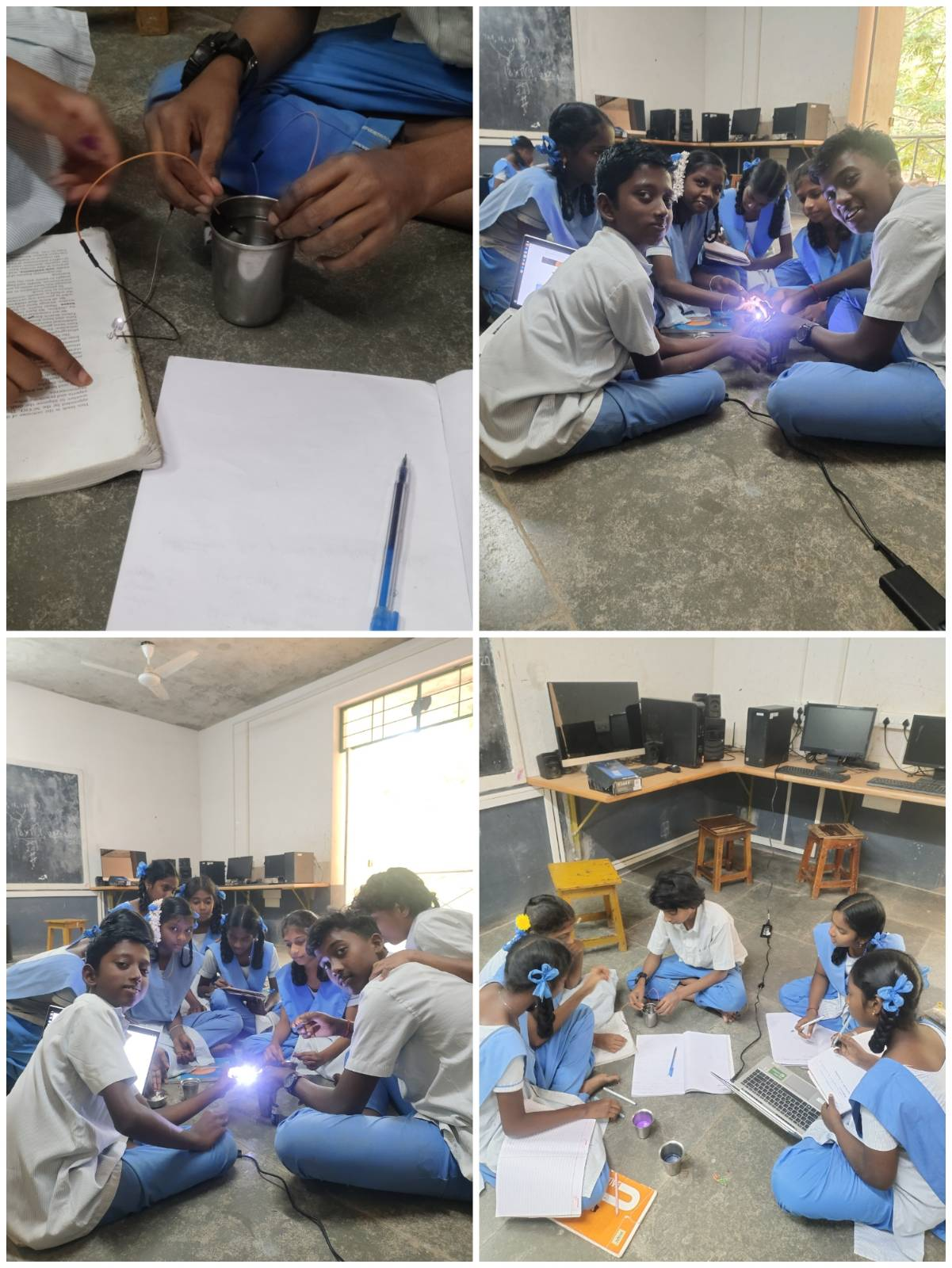
Learning Ethernet Crimping Through Peer Learning at NESS School
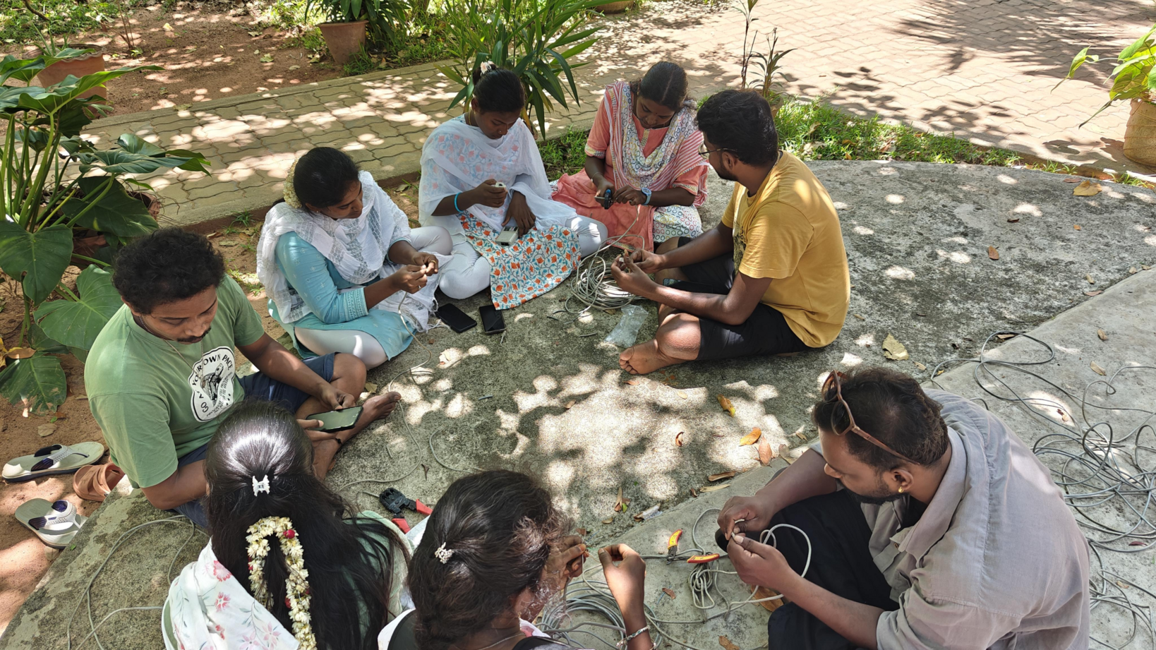
-Vaishnavi, Poongzhali, Atchudhan, Arunkumar, Aarthi, Nithya Sandhosh, Preethi P, Ajay On 19th May, we from STEM Land visited NESS School for Ethernet wire checking and hands-on learning. There were eight members in our team, and among us, Ajai and Atchudhan already knew...
Read out all