STEM Land Brochure
Stemland Guests
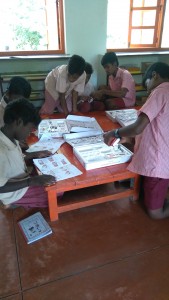
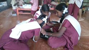
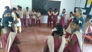
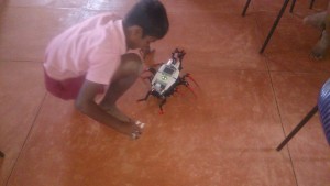
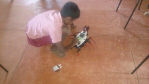
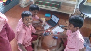
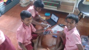
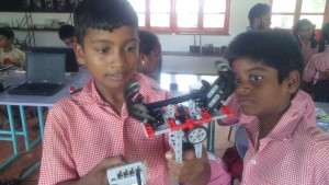
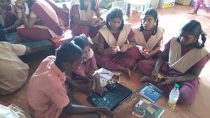 Children from Govt school, Edayanchavadi visited us one day in April 2016. They interacted with Udavi children. Some of them showed them how to do the Rubiks cube. They were taught Abalone and other games. Some made the Bigshot cameras and some worked on a robot that was transferred into a guitar. Looked like they had good fun!
Making a Model of a Generator
Along with the 6th graders in Udavi we had created a working model of a generator using a motor. The motor was connected to a pulley and routed to the cycle wheel. In turn when the wheel was rotated it produced electricity to power up the India map the students created with LED’s they also figured out that the LED’s did not glow in both direction of rotation of the wheel they found that there was tow terminals to the LED (Anode and Cathode) and it was different from normal bulbs. All the LED’s where connected in parallel to each other. with the generating power source in series.
link: https://youtu.be/DRLzvMe2RBE
StemLand-Name Board
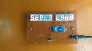
At first the children did a seven segment display(SSD) board which displays StemLand on it by lighting it up using a 9V battery using a corresponding resistor in series. After that we(Anishvathi,Sangeetha,Praveen,Sharmila,Fevina- 8th Grade Students) properly soldered the SSD on a pcb board . We wanted to make the ssd to light up in various ways. So, we used an arduino pro-mini to program the SSD to blink in various ways .We used a battery which was 9V but if we had given the 9V directly it would burn out the arduino board and the SSD.So, we used a 5V voltage regulator which will give us 5V at the output from a 9V input from the battery. Where the output of the regulator is fed to the input of the arduino board. The board worked smoothly. After a few days the battery discharged so we had to change a new battery .
Then Sanjeev gave an idea to make it work using the solar panel . At first Praveen (Student form 8th Grade) and I used one solar panel which did not have enough current to light up the SSDs.So, we used two solar panels in parallel and we got enough current to light up the SSD. Now the board runs in solar energy from the solar panel.
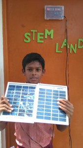 (Praveen holding the solar panel and displaying how it works)
There is also more detail about this Name Board in the link below
http://www.auraauro.com/showcase/name-board-of-stem-land/
2nd Assessment – 9th grade
Self-Assessment 9th grade
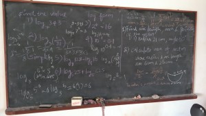
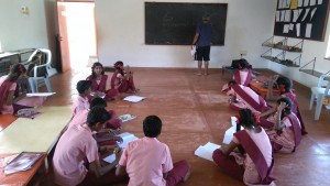
The children of 9th grade were given a self-assessment ‘test’ to make them understand where they are. 4 questions were given on the chapters that they had been working on so far(logarithm and scientific notation). The children were allowed to discuss among them. They graded themselves. We didn’t ask them for marks or how they performed. They would have known it themselves. It was just a reminder on what they are required to know.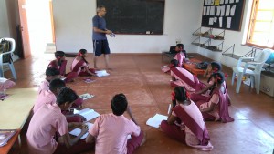
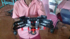
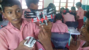
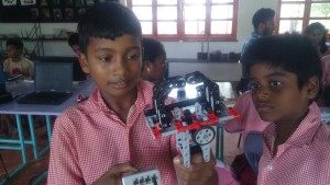
Making of SPIK3R
Creating a Power Supply
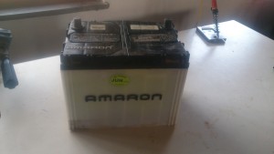
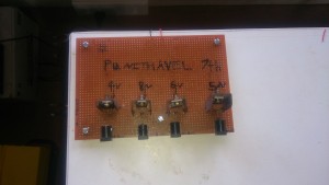
In Stemland we got a car battery that was used, and to put it to use we came up with a project of creating a Power supply with various output voltages. To drive different Circuits with the different potentials. This Project was taken up along with Punithevel (7th std student from Udavi). So to get started, we put together a plan with four output’s. then we decided on the components that we needed and made a list. It consisted of four different power IC’s, connectors and adaptors along with wires. Punithevel had to look up the data sheets of the Power IC’s to figure out the pin configurations for them. Then he came up with the following circuit design.
 The fun part started here when we tried to hook it up on a PCB all the adaptors pins were too big for the given hole on the PCB. Then we put use of our driller set from Stemland and made the required hole at various points on the boards.
The following days we were going through the electronic circuits boards that we have from used devices and decided to de-solder some cool looking heat sinks and salvage them for our circuits 🙂
All the wirings were done taking black for the negative terminal and red for positive terminal. once done the wiring were fragile, and came off when handled roughly. We had the right solution 🙂 the heat gun was put use and the board became robust.
Then we hooked up our board to the work bench again drilling holes and screwing them firmly. following is a picture of the PCB created. We tested it with a multimeter and got the expected output’s, now It works 😉
