Another Battery Model Using Water…..

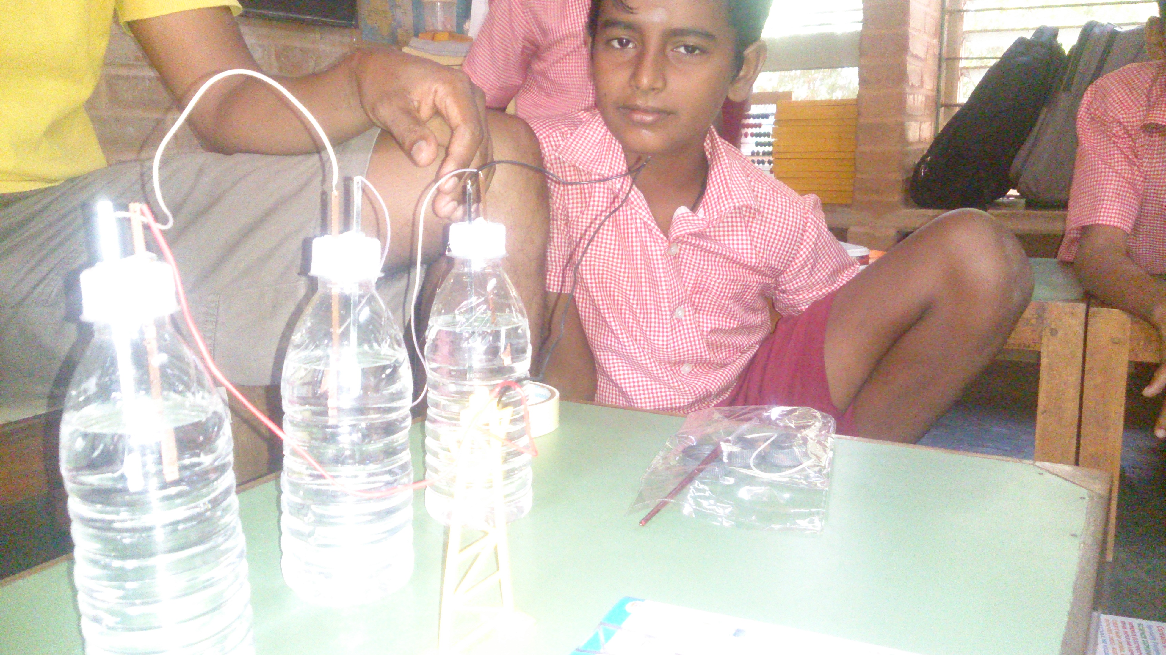
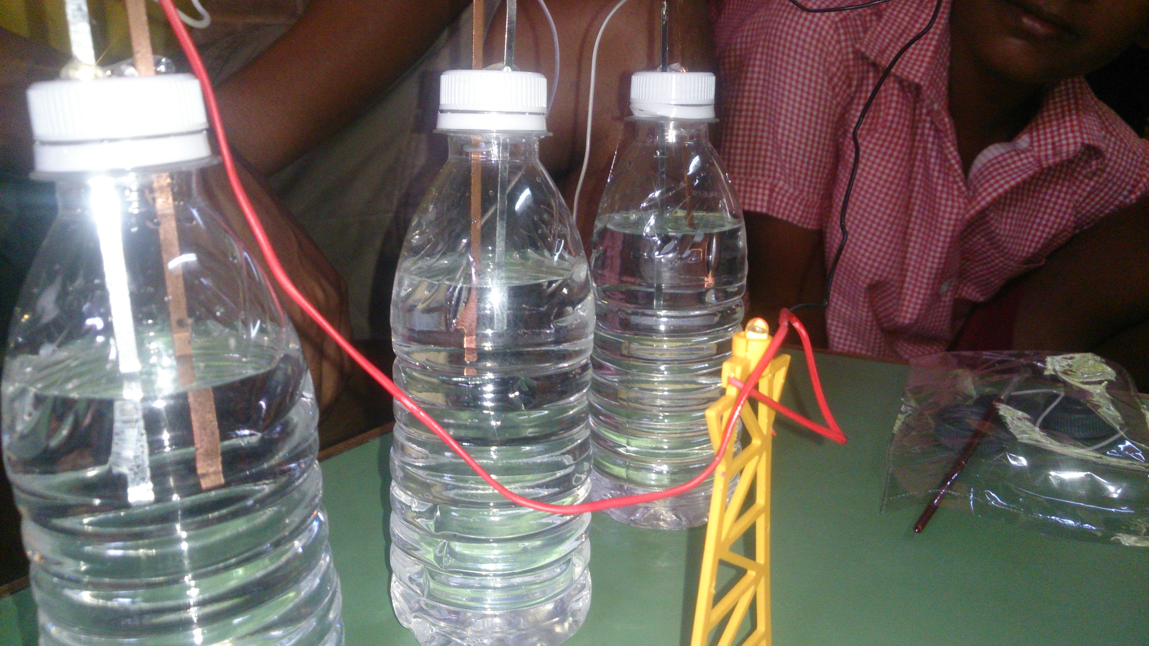
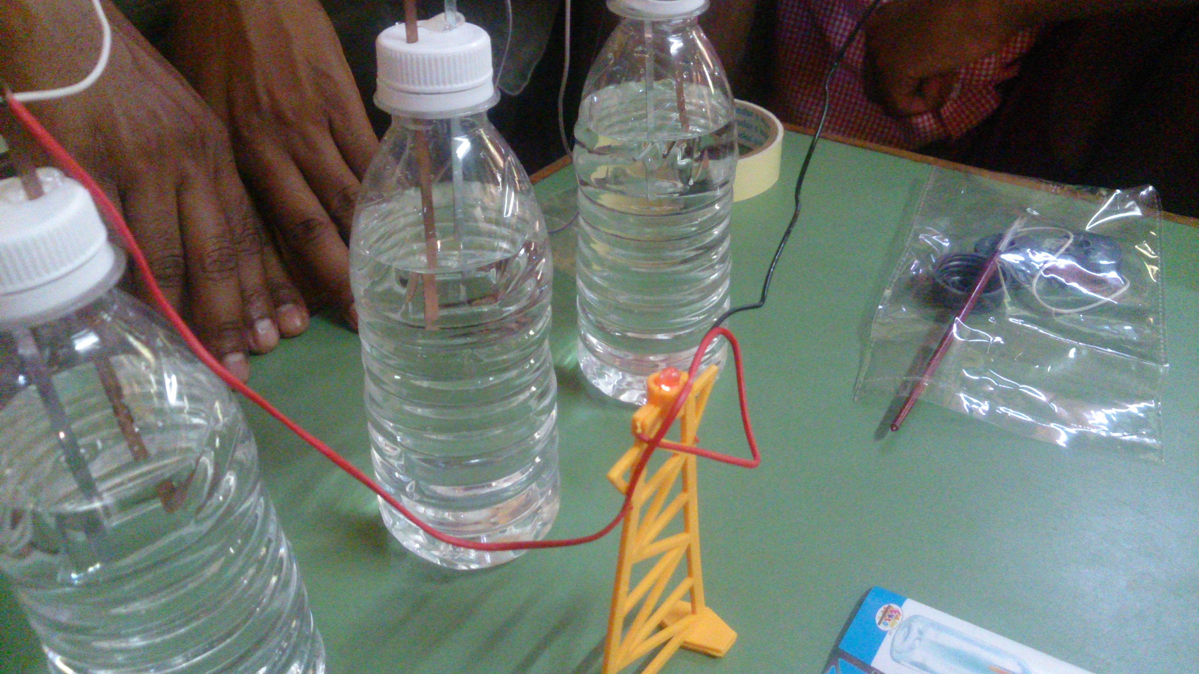
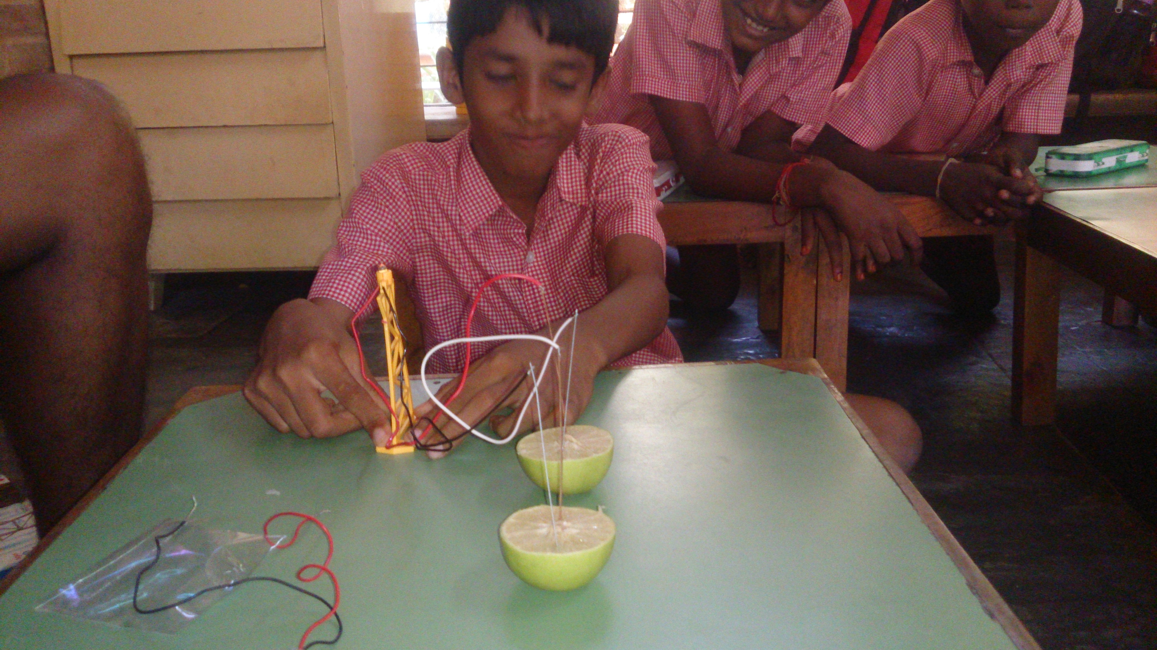
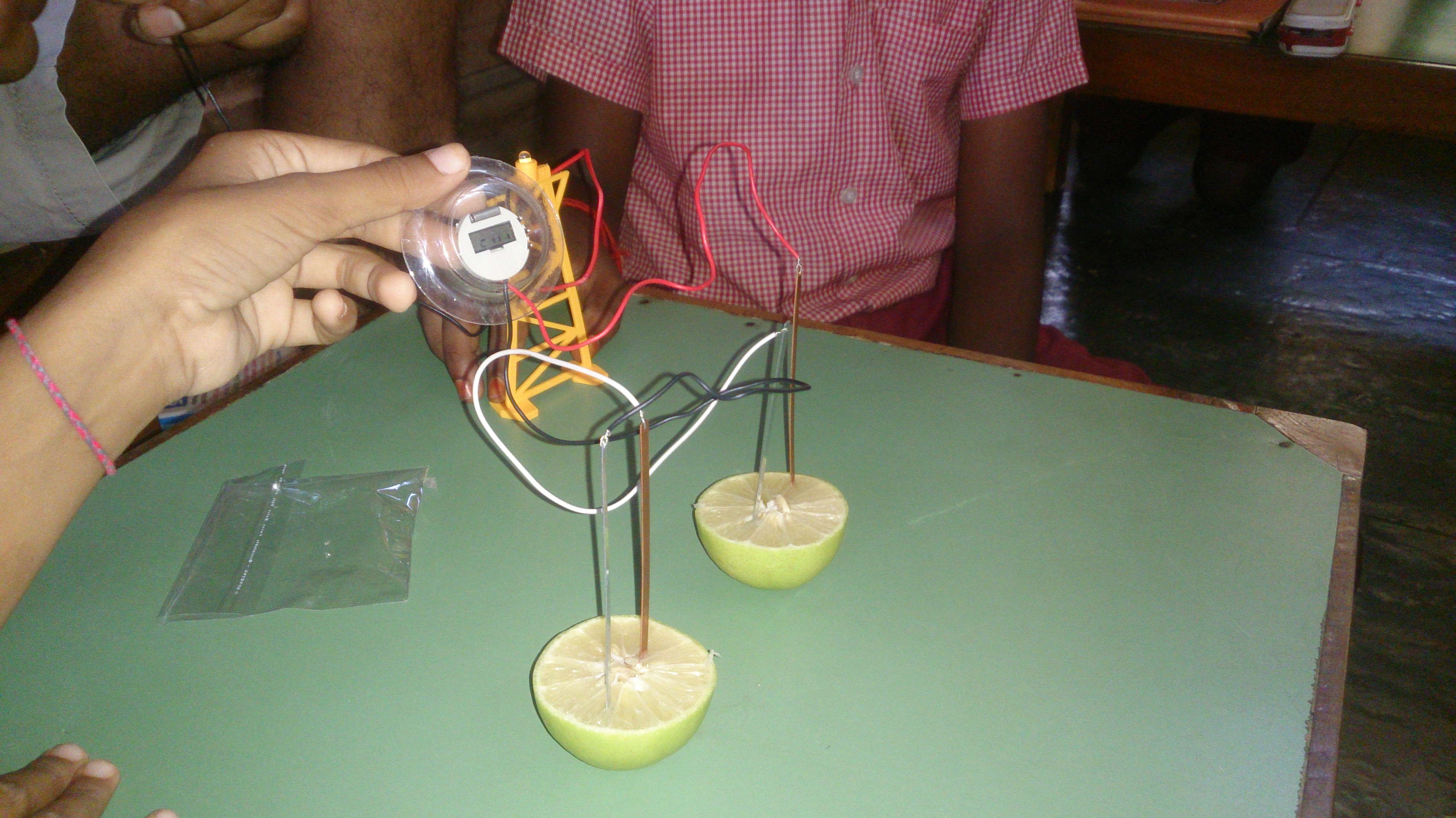
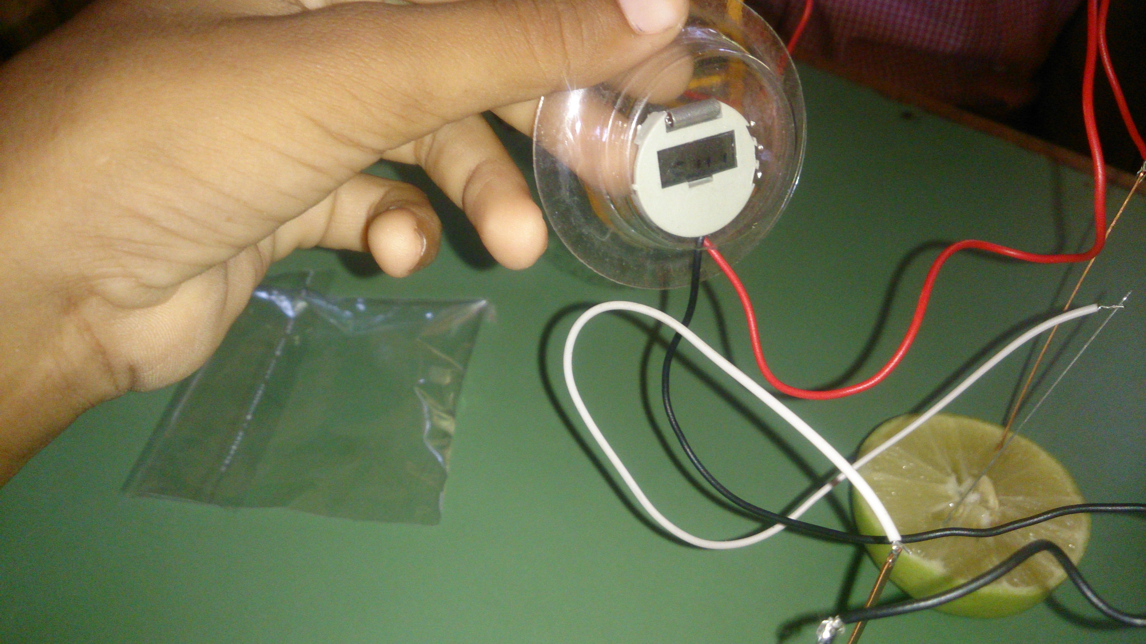
The following class a similar battery model was shown and the children figured out on how to connect the rods ( Cu and Zn ) so that electricity could flow from one bottle to another and so on until the terminals reached the led tower, thus building a small battery unit to power the led up. the children found out that the rods should be kept in series manner to achieve the working of the experiment. They also noted that the copper rods colour was fading eventually with time.

DSC_0807 DSC_0808 DSC_0811


Building a Battery model

The sixth grade children are super interested when you do something new in class, that’s what happened when we all together build battery models using lemon, copper and zinc rods to produce sufficient electricity to turn on a led 😉 and a digital watch.

DSC_0798DSC_0797

DSC_0794DSC_0796


Disentanglement Puzzles with the Sixth Graders

At Stem Land we have a huge collection of disentanglement puzzles, and the students decide that they had to figure them out. The atmosphere was covered with low conversations and sudden bursts of joy, suddenly a child will be ‘like  yeah i figured it out’ Then the part came when you would become confused again, in order to put it back together the same way it was. This was the tricky part 😉 .

DSC_0748 DSC_0749 DSC_0750 DSC_0751


The children and their teacher really enjoyed solving together, so did I 🙂 .

Building a miniature Catapult

Along with a Sixth Grader, who was interested in medieval times, and so came the thought of building a miniature catapult with him. It consisted of blocks and nylon ropes that acted as the torsional element.

DSC_0764DSC_0767

DSC_0763after building it, he tried a few test fires and realised that the distance covered by the load (wooden Ball) was not as expected.

Then a few more twists were added to the rope and the Catapult started to really acquire a huge range in its firing capacity.

When i was a little shorter and a little smaller 😉  ‘Age of Empires’  is what i was into during my week ends.

This was a really beautiful refresher along with Ablilash 🙂 to physically build and learn how the catapult was used to haul heavy pay loads over a distance during sieges in the middle ages.

physics_catapult_4


Creating a Spice Model from a .subckt file

The following video demonstrates on how to create a spice model of a component, from a .subckt file which can be acquired from the retailer.

following is a spice model file for a bridge rectifier ; mb6s

data sheet : MB6S_MCC

– Open LtSpice

– Browse for the file and open

– Once opened right click .subckt and create model and design your circuit.

-Ref : http://www.linear.com

Op-Amp positive feedback design

The following circuit has a voltage source that operates between 3V and 5V and is connected to the Op Amp’s positive input, across a resistor divider R2 and R1 at the node Va. The simulation is run for 200m secs.

opamp_gnd

The design is as following: applying super position

1

2

3

4

5

6

7

8

9

Following is the Spice file :  opamp_gnd

Video :Positive Feedback


LtSpice – Introduction

LTspice IV is a high performance SPICE simulator, schematic capture and waveform viewer with enhancements and models.

The simulator software can be downloaded from the following link:

ltspice.linear-tech.com/software/LTspiceIV.exe

The following is a circuit on how to use a switch ” .model ” in simulations, it has been created for a RC circuit.sw

As seen these switches are not a physical model, they require a initial voltage to start to act as one.

20150820_switch_RC is the simulation file for the given circuit, can be seen by installing LtSpice.


Every switch has some instance of resistance when on or off;
Ron = 1            ‘ the resistance when the switch is turned on.’
Roff = 10meg   ‘ the resistance when the switch is turned off.’
Vt    = 0.1         ‘ the instance when the switch turns on’

Classical way to solve the RC filter in time domain :

RC filter classical time domain way


Programming the Deek Robot

The Deek robot is similar to the Arduino pro mini with a ATmega 328. it has no USB interface. i used the Arduino UNO to program the Deek robot, without removing the micro controller ATmega 328 from the UNO board.

1. Connect the Arduino UNO and upload the program

2. Connect jumpers as follows
Arduino      UNO               –>         pro mini
RESET             –>         GRN
RX                   –>         RXD
TX                   –>         TXD
5V                   –>         VCC
GND               –>         GND

GND             –>           BLK

Arduino      UNO               –>         DEEK_ROBOT
RESET             –>         RESET
TX                   –>         TXD
5V                   –>         VCC
GND               –>         GND

GND               –>         GRD

Now using Arduino UNO as an ISP, from the Tools, Programmer .

and selecting the board as Arduino Pro or Pro mini (5V,16Mhz)w ATmega 328, from the Tools, Board.

Upload the program.

USING FTDI to program;

FTDI                –>         DEEK_ROBOT
RX                   –>         TXD
TX                   –>         RXD
5V                   –>         VCC
GND               –>         GND

Dt                   –>         DTX

Now  use AVR ISP, from the Tools, Programmer .

and selecting the board as Arduino Pro or Pro mini (5V,16Mhz)w ATmega 328, from the Tools, Board.


Tabulating the obtained values

        The frequency and the sine wave was set by the function generator. The input, output wave forms were observed from the CRO. The conditions taken were  a 50KΩ , 1KΩ and a current source. The input was fed to the 2.1 speaker’s connector jack to produce the sound of the fed sine wave.

Frequency

(Hz)

Input

(peak to peak value)

Conditions

Output

(Peak to peak value)

Observations

600

2 V

50 KΩ

0.2 V

Distorted wave

600

2 V

1 KΩ

2 mV

Small signal with distorted wave

600

2 V

Current Source

100 mV

Distorted wave

600

5.5 V

Current Source

300 mV

Not distorted

600

5.5 V

50 KΩ

100 mV

Partially distorted

600

5.5 V

1 KΩ

5 mV

Bottom of the wave distorted

450

11 V

1KΩ

8 mV

Distorted wave

450

11 V

50 KΩ

200 mV

Extremely distorted wave

IMG_20150511_111205IMG_20150511_111439

From the tabulation the maximum output 300mV is achieved when the input is set to a peak to peak value of 5.5V connected from the current source (PNP BJT’s collector junction ).

5To determine the amplification,

the voltage at the base of the NPN transistors is ≈ 2.5V. now divided by the resistance of resistor R6 gives us the current.

amp

 now, the obtained current value multiplied by R5amp1

gives the amplified output ≈ 5V.